Transmit/receive switching circuitry with improved radio frequency isolation

Active Publication Date: 2015-10-15
KONINKLJIJKE PHILIPS NV
View PDF12 Cites 7 Cited by
  • Summary
  • Abstract
  • Description
  • Claims
  • Application Information

AI Technical Summary

Benefits of technology

The invention is a circuit that controls when a magnetic resonance imaging (MRI) machine's RF antenna should transmit or receive signals. The circuit improves the isolation of the RF signals, which means it blocks out other signals that may interfere with the MRI data. This results in better quality MRI images. The circuit also allows for more flexibility in designing the MRI machine, which can make it easier to build and modify.

Problems solved by technology

For this reason, a second stage ST′ has to be added, which increases complexity and physical size of the T / R switch.

Method used


Image

  • Transmit/receive switching circuitry with improved radio frequency isolation
  • Transmit/receive switching circuitry with improved radio frequency isolation
  • Transmit/receive switching circuitry with improved radio frequency isolation

Examples


Embodiment Construction

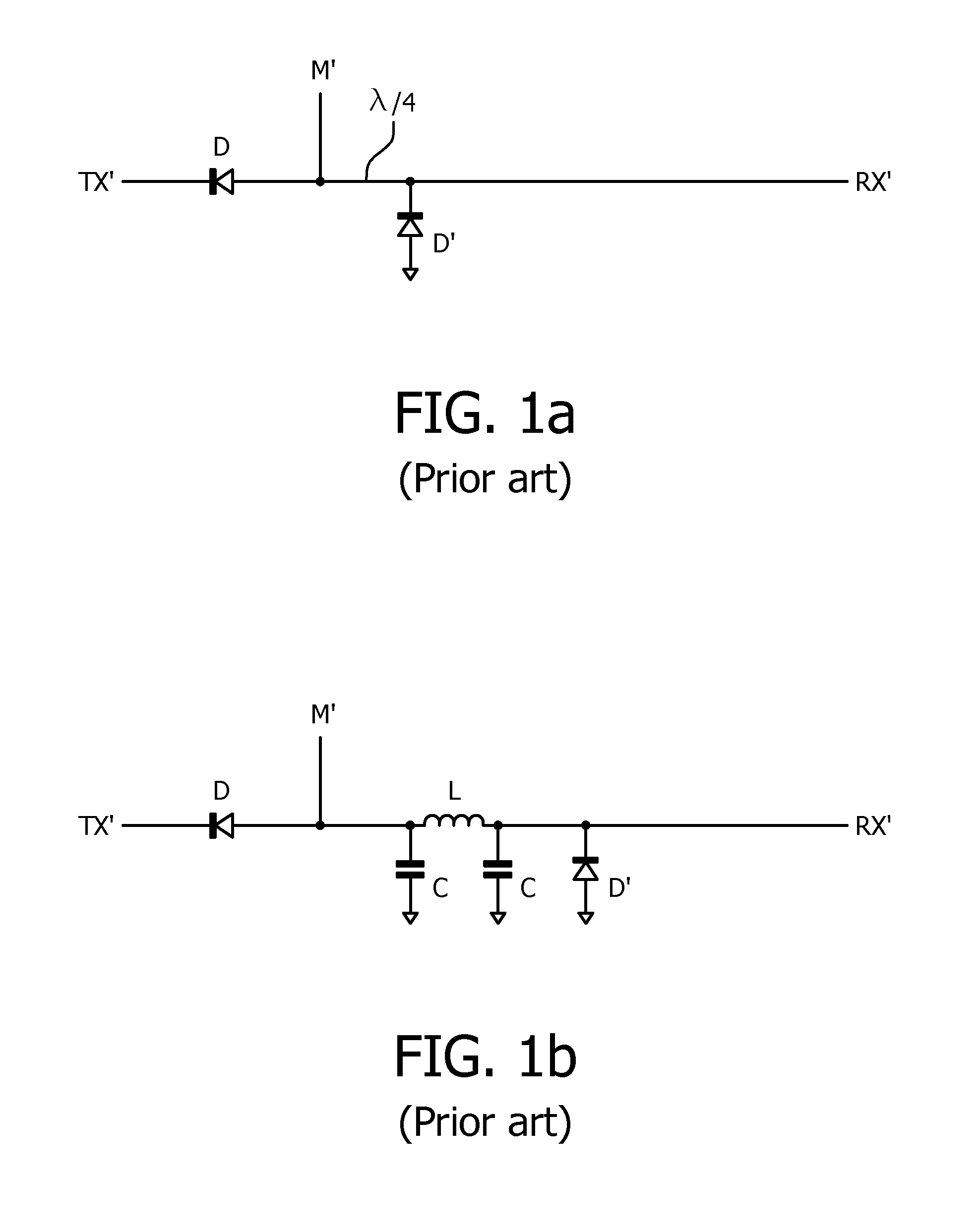
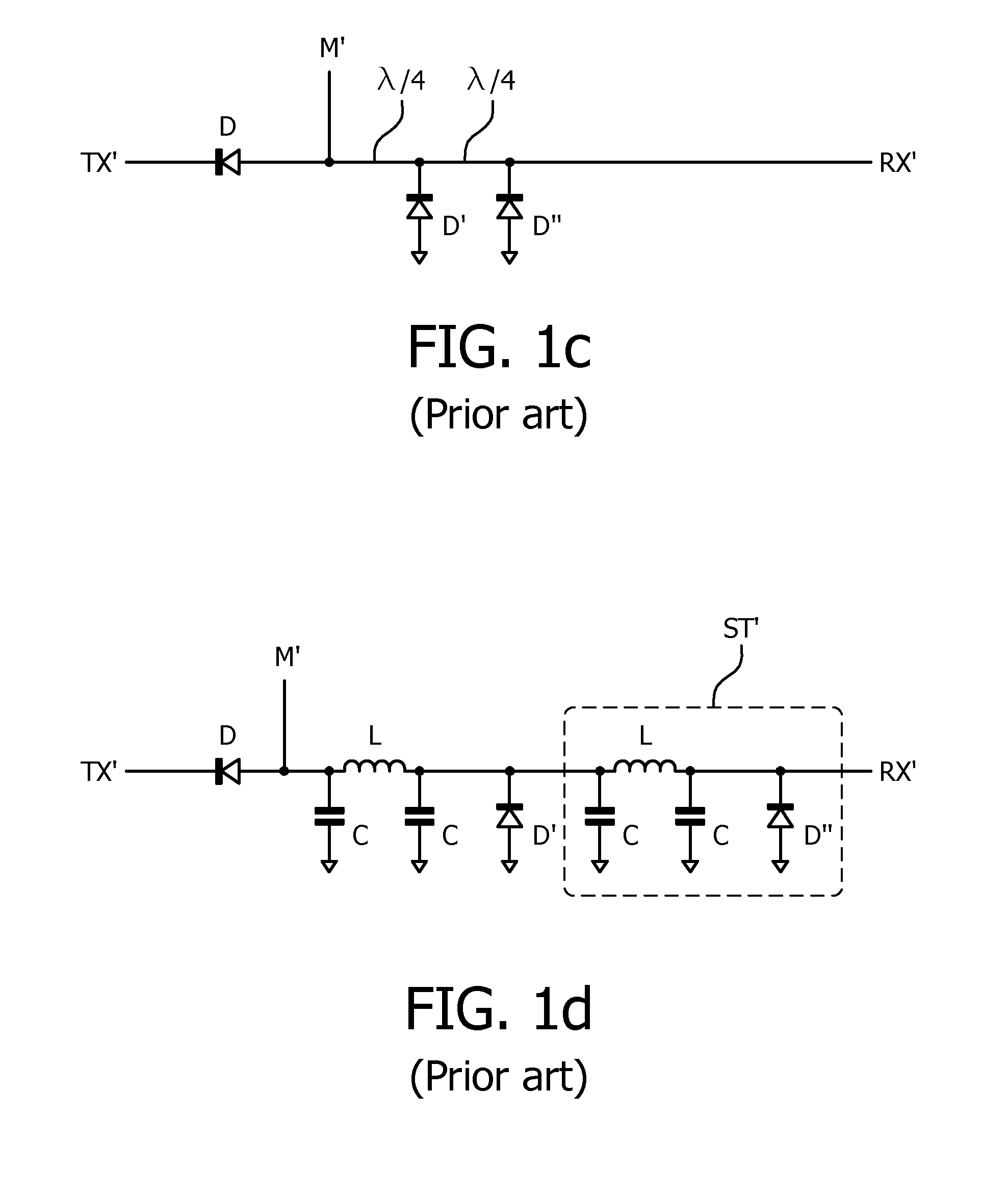
[0069]FIGS. 1a to 1d illustrate prior art transmit / receive switches which have been depicted in the introductory section already.

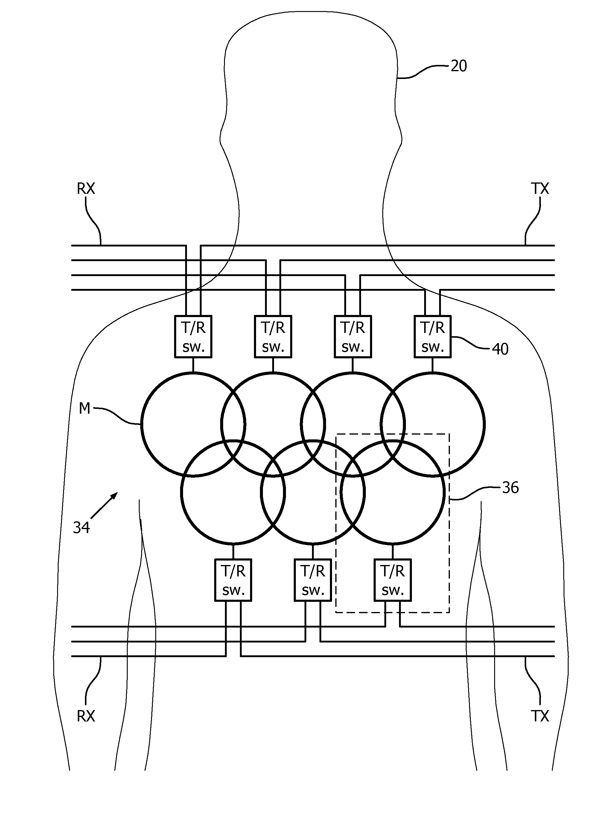
[0070]FIG. 2 shows a schematic illustration of a part of an embodiment of a magnetic resonance (MR) imaging system 10 in accordance with the invention, comprising an MR scanner 12. The MR scanner 12 includes a main magnet 14 provided for generating a substantially static magnetic field. The main magnet 14 has a central bore that defines an examination space 16 around a center axis 18 for a subject of interest 20, usually a patient, to position within. It should be noted that, in principle, the invention is also applicable to any other type of MR imaging system providing an examination region within a static magnetic field. Further, the MR imaging system 10 comprises a magnetic gradient coil system 22 provided for generating gradient magnetic fields superimposed to the static magnetic field. The magnetic gradient coil system 22 is concentrically arranged wi...


PUM


Abstract

A transmit / receive switching circuitry (40; 48) for a magnetic resonance radio frequency antenna (M) for use in an magnetic resonance imaging system (10), the transmit / receive switching circuitry comprising: -a radio frequency input transmission line (TX) provided for transmitting radio frequency power to the magnetic resonance radio frequency antenna (M) and a radio frequency output transmission line (RX) provided for transferring away magnetic resonance signals received by the magnetic resonance radio frequency antenna (M) at a magnetic resonance frequency from the magnetic resonance radio frequency antenna (M);—a parallel resonant circuit (42) with a resonance frequency that is substantially equal to the magnetic resonance frequency, and that is connected in parallel to the magnetic resonance radio frequency antenna (M) with regard to the radio frequency input transmission line (TX),—a series resonant circuit (44) with a resonance frequency that is substantially equal to the magnetic resonance frequency,and that is connected in series between the radio frequency input transmission line (TX) and the radio frequency output transmission line (RX); for providing improved radio frequency isolation between the radio frequency input transmission line (TX) and the radio frequency output transmission line (RX); a method for generating consecutive RF transmit periods and RF receive periods of the magnetic resonance imaging system (10) using such a transmit / receive switching circuitry (40; 48); a switching control unit (32) having at least one such transmit / receive switching circuitry (40; 48), for use in the magnetic resonance imaging system (10); a software module (26) for controlling an execution of such a method.

Description

FIELD OF THE INVENTION[0001]The invention pertains to a transmit / receive (T / R) switching circuitry for a magnetic resonance (MR) radio frequency (RF) antenna for use in an MR imaging system.BACKGROUND OF THE INVENTION[0002]In the field of magnetic resonance (MR) imaging, it is known to employ MR radio frequency (RF) antennae that are provided for transmitting RF power at a resonance frequency for resonant excitation of nuclei in a subject of interest during a first period of operation, and for receiving MR RF energy emitted by the nuclei at a second period of operation that is different from the first period of operation.[0003]In the state of the art of operating an MR imaging system, periods of transmitting RF power and periods of receiving magnetic resonance imaging signals are taking place in a consecutive manner during an MR imaging session. The periods of transmitting RF power and periods of receiving MR imaging signals may be generated by controlling the MR antenna by transmit...

Claims


Application Information

Patent Timeline
IPC IPC(8): G01R33/36G01R33/54
CPCG01R33/543G01R33/3664H04B1/44
Inventor LIPS, OLIVER
Owner KONINKLJIJKE PHILIPS NV
Why Eureka
Try Eureka