
Method and arrangement for local synchronization in master-slave distributed communication systems

a distributed communication system and master-slave technology, applied in data switching networks, time-division multiplexing selection, multiplex communication, etc., can solve the problems of requiring some complexity overhead, is not easy to achieve, and is generally more complex and less efficient than single-stage switches. achieve maximum throughput, ample time, and high bandwidth

Inactive Publication Date: 2010-05-18
INT BUSINESS MASCH CORP
View PDF25 Cites 6 Cited by
  • Summary
  • Abstract
  • Description
  • Claims
  • Application Information

AI Technical Summary

Benefits of technology

[0015]Another objective is to provide a means to locally and independently measure the propagation delay difference between the data and the control paths at every synchronization point of the distributed system. This local measurement allows to cope with the inherent speed scalability limits of distributed communication systems with centralized control, by enabling the system to operate in a locally synchronous but globally asynchronous fashion. The advantage of this scheme, as opposed to a global synchronization scheme of a master and multiple slaves, is that the centrally controlled system can be scaled to operate with higher degree of parallelism, arbitrary number of slaves and arbitrary topology. In particular, it allows to build plesiochronous systems that operate different modules with slightly different frequencies of slowly varying phases, which is usually the case in large distributed systems.
[0026](c) in the one or more slave units, compensate for the propagation delay difference, represented by the time shift information obtained in step (b), by delaying for each received packet segment either the packet segment itself or the derived control information.
[0027]A particular advantage of this invention is that its synchronization scheme is locally self-adaptive and that it can be made robust. Self-adaptive means that the synchronization process is performed locally and autonomously at every synchronization point of the distributed system, and that no bi-directional communication is required between neither module of the communication system. Robustness to varying delays of data and / or control paths can be achieved by sending the synchronization packets multiple times through the system, for example at regular intervals.
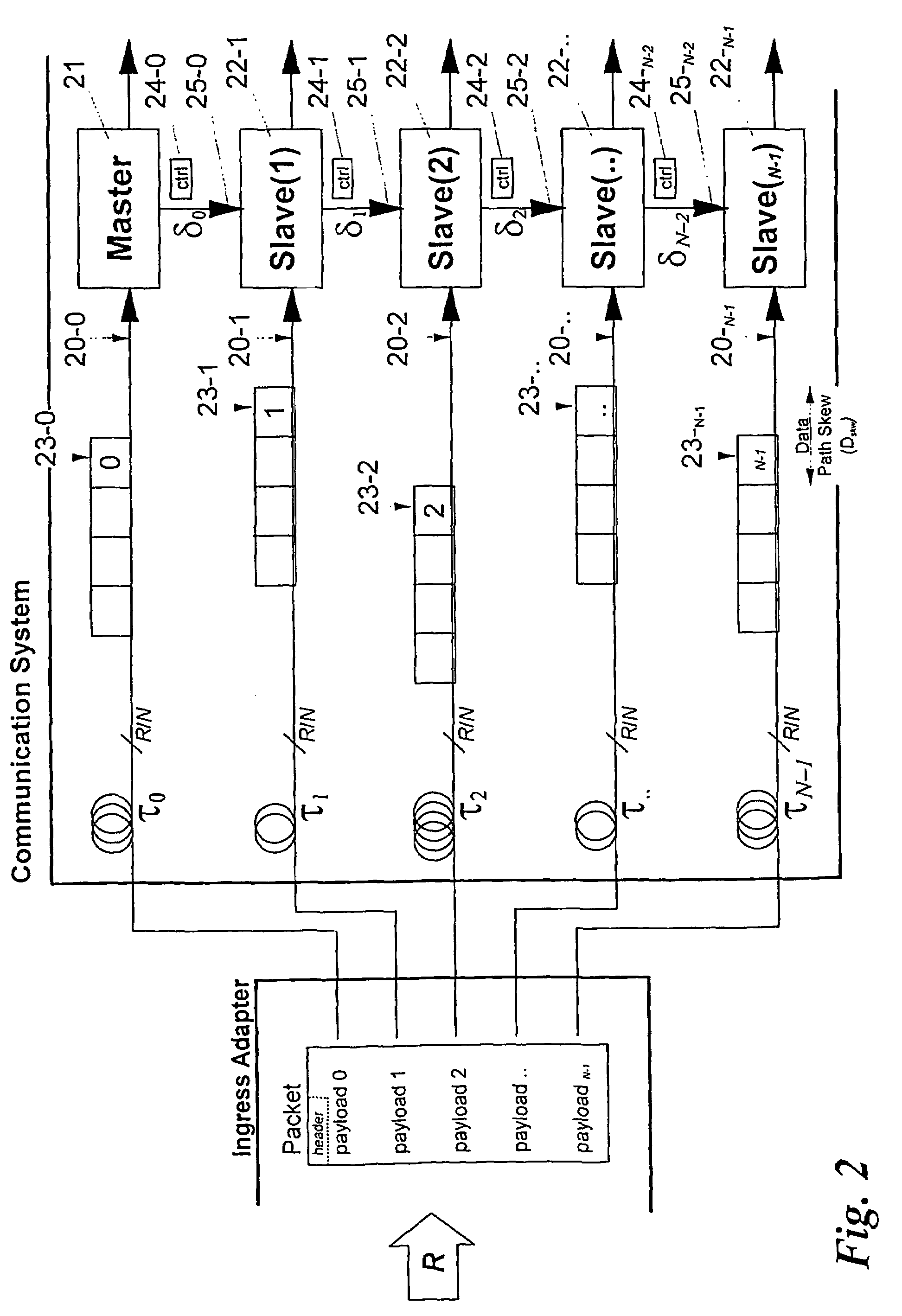
[0028]A further advantage of this invention is that, since the master / slave segments can compensate for skew between packet segments, the ingress adapter source is not required to transmit all packet segments simultaneously. In fact, it is advantageous for it to send the packet segments transmitted to the master and the slaves at a time delayed by the time required for the previous master / slave on the control path to forward the control information to the following slave in the path plus the difference between the data path skew of those consecutive segments on the control path. Doing this decreases the amount of buffering required on the data path of the slaves to compensate for the control path latency. This advantage holds for single-stage systems or the first stage of a multistage communication system.
[0029]The advantage of the relaxed synchronization constraints per stage give more design freedom for the master plane in both, single- and multistage systems because the master plane is now temporally independent from the self-adapting slave planes. The advantage of local synchronization in multistage systems is that no extra latency is added by each stage, which would be the case if each stage were globally synchronized. Because multistage communication systems are also physically larger than single-stage systems (in identical technology), relaxed synchronization constraints become more important for such systems because the larger system may span multiple boards / shelves / racks that are connected through longer links. With ever increasing bandwidth / faster packet transmission times, the decoupling of synchronization constraints from packet lengths is an important advantage.

Problems solved by technology

The second option is the multistage switch architecture which provides higher throughput by means of more parallelism, but which is generally more complex and less efficient than single stage switches.
Its main drawback is that it requires some complexity overhead incurred by load balancing and reordering algorithms that handle the packets distributed over the multiple switch domains.

Method used


Image

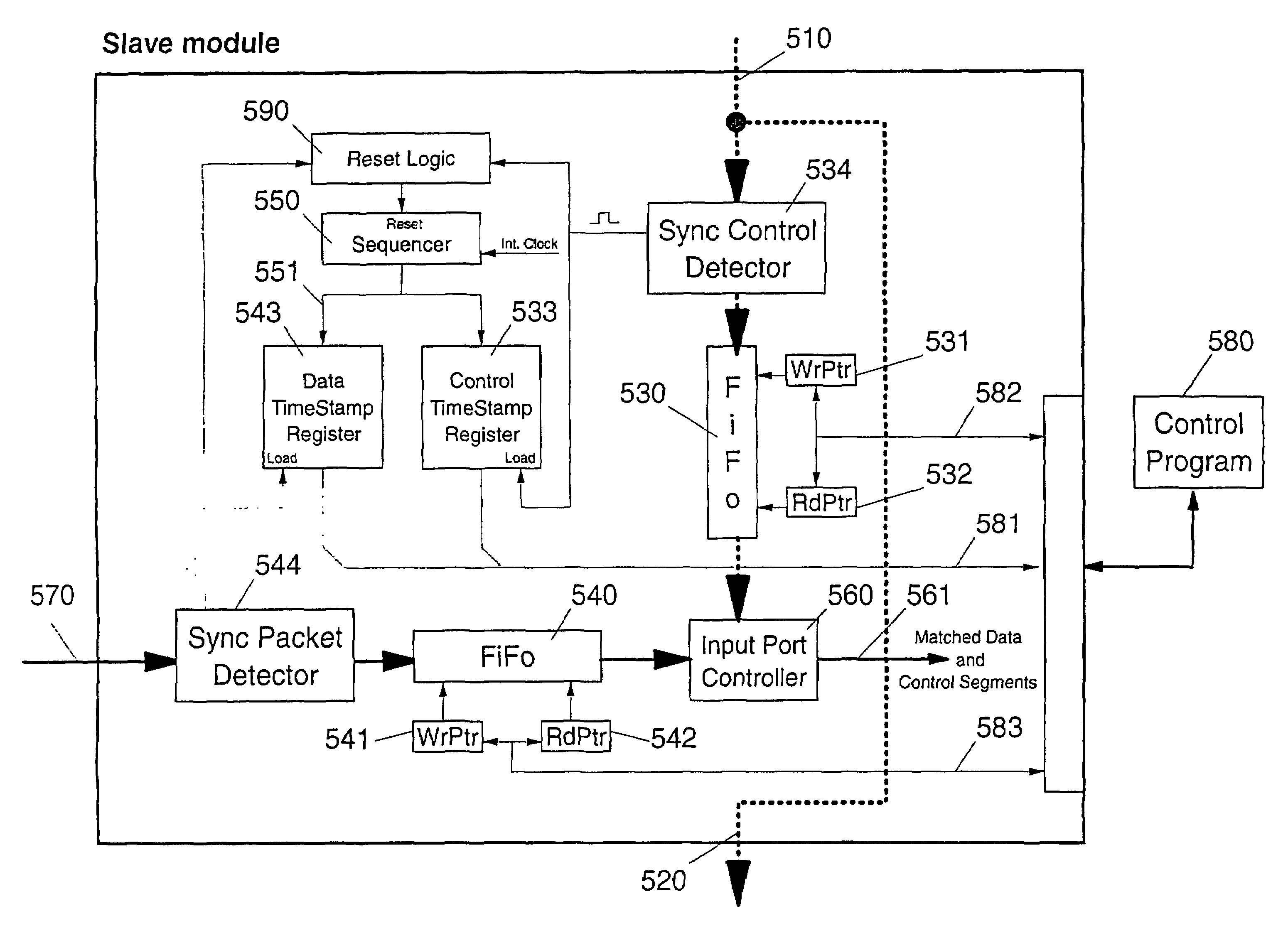
  • Method and arrangement for local synchronization in master-slave distributed communication systems
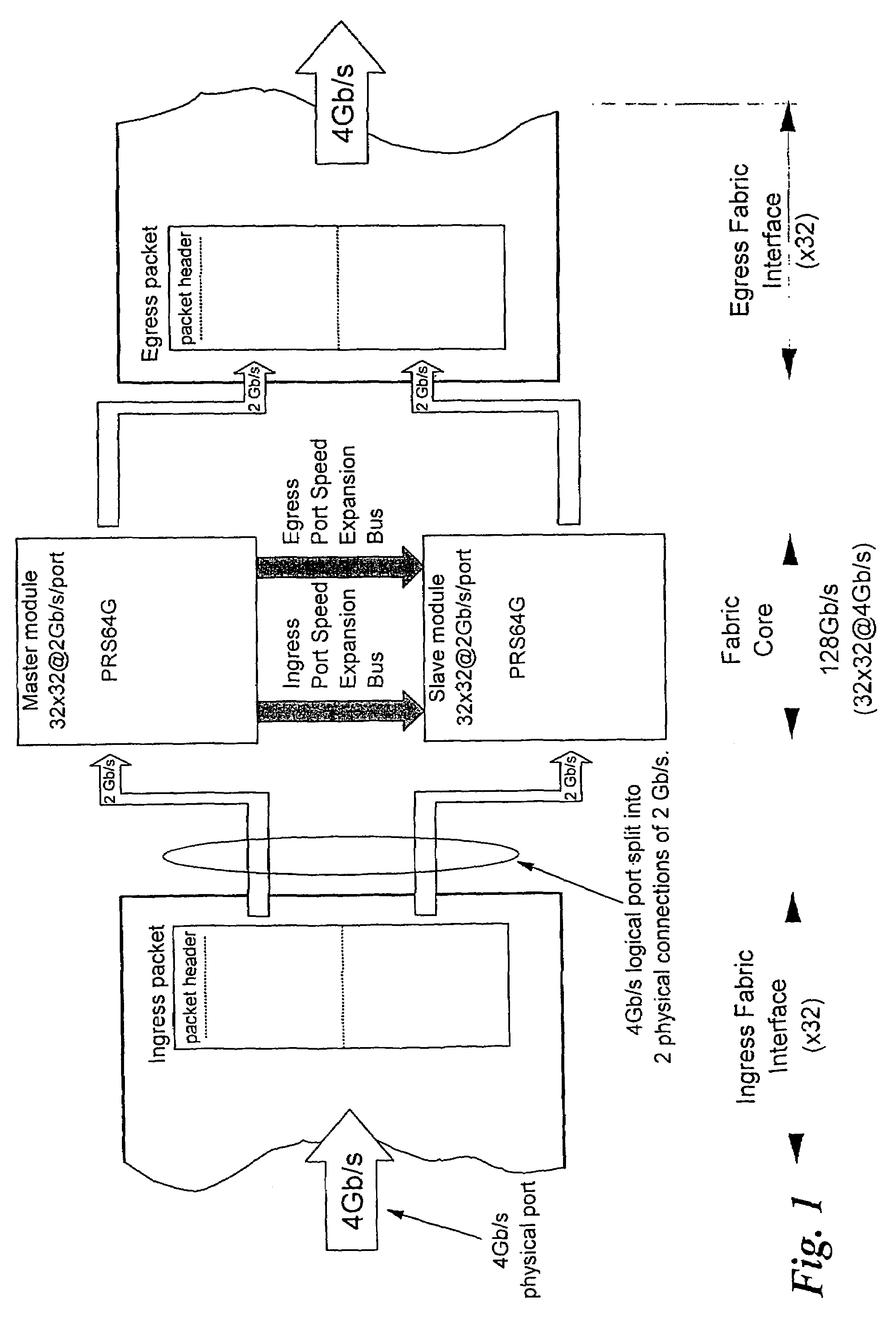
  • Method and arrangement for local synchronization in master-slave distributed communication systems
  • Method and arrangement for local synchronization in master-slave distributed communication systems

Examples


Embodiment Construction

[0038]With general reference to the figures and with special reference now to FIG. 3, a general communication system 30 that transports data entities, hereafter called packets, is considered. Beyond certain stringent requirements of size or performance, parallelism is sometimes the only feasible solution in any given technology.

[0039]Parallelism can be achieved by partitioning and distribution of the system. The combined functionality of the distributed parts 30-1 to 30-N, is identical to the functionality of the original system 30. Therefore a packet 31 is also partitioned (into segments) and transported through the communication system by processing different parts of the packet in different parts of the system. Partitioning of the system and the packet is depicted in the lower part of FIG. 3. A typical example of such a parallel system is the case where M=N and each segment of a packet is processed by a corresponding part of the communication system.

[0040]Segmentation of the inco...


PUM


Abstract

For switching or transmitting data packets, one can provide communication systems which consist of several modules —operating in parallel on segments of a packet —to increase speed and handling capacity. One module acts as master, others are slave modules controlled by control signals derived by the master module. It is important to correctly synchronize in each module the data segment and the respective control signal of each packet, because in large systems the data paths carrying packet segments and the control signal paths may have substantially different delays. The invention provides for measurement of the propagation delay differences and for introducing a controlled delay in each slave module, so that data segments and control signals can be correctly correlated by delaying either the one or the other. Synchronization packets are transmitted besides normal data packets, for obtaining time stamps which are used to determine the delay difference.

Description

CROSS REFERENCE AND PRIORITY[0001]This application filed under 35 USC 371, is cross-referenced with, and claims priority from, International Patent Application PCT / IB2003 / 01227 filed on Apr. 30, 2002, and published in English with Publication No. WO2003 / 094446 filed on Jul. 24, 2003, under PCT article 21(2), which in turn claims priority of EP 02009738.2, filed on Apr. 30, 2002.FIELD OF THE INVENTION[0002]The present invention relates to packet handling technology in electronic communication networks and the design structure of the processing arrangements used therefor. More particularly it refers to a method and apparatus for synchronizing multiple processing elements (or modules) operated in parallel, to form the equivalent of a single processing arrangement with aggregate throughput equal to the sum of the combined aggregate throughput of multiple parallel processing elements. A typical application of this invention is in packet switching systems.INTRODUCTION[0003]Among all the c...

Claims


Application Information

Patent Timeline
Patent Type & Authority Patents(United States)
IPC IPC(8): H04L7/00H04L12/56H04Q11/04
CPCH04L49/153H04L49/254H04L49/45H04L49/3081H04L49/3072H04L49/3009
Inventor COLMANT, MICHAELBENNER, ALANABEL, FRANCOIS G.PORET, MICHELSCHUMACHER, NORBERTBLANC, ALAINVERHAPPEN, MARKGUSAT, MITCH
Owner INT BUSINESS MASCH CORP
Learn More