Engine balance masses and drives

a technology of balance mass and engine, which is applied in the direction of machines/engines, gearing details, mechanical apparatuses, etc., can solve the problems of unbalanced inertial moments and/or forces, unfavorable noise vibration, and significant space occupied by balance shafts in engine blocks, so as to achieve the effect of reducing the weight and packaging space of the balance mass

Active Publication Date: 2012-07-03
FORD GLOBAL TECH LLC
View PDF13 Cites 16 Cited by
  • Summary
  • Abstract
  • Description
  • Claims
  • Application Information

AI Technical Summary

Benefits of technology

[0005]In this way, it is possible to drive the balance shaft via one or more gears to provide desired rotational speed (e.g., to match the timing of the crankshaft) and reduce packaging space. Further, the first example may include additional gears configured as a planetary gear set.
[0007]By utilizing a planetary gear set, it is possible to provide a compact drive that minimizes weight and packaging space of the balance mass and drive while enabling the balance mass (such as a balance shaft) to be driven at a desired speed and in a desired direction. The balance mass may include balance shafts disposed in a camshaft as well as additional masses such as weighted gears or pendulums included in the output gear, providing flexible placement of the balance mass and drive and easy adaption of such a balance mass and drive across a range of engine configurations (including “V” configurations, “I” configurations, 3, 4, 5, 6, 8, 10 and 12 cylinder engines, etc.).

Problems solved by technology

The rotational motion of a crankshaft in an engine, along with additional connected mechanical parts such as crankpins, connecting rods and the like may produce unbalanced inertial moments and / or forces.
These moments and / or forces may lead to undesirable noise vibration and harness for a vehicle operator.
However, the inventors herein recognize various issues related to such an approach.
Balance shafts may occupy significant space in an engine block, such as when placed in a valley of a “V” engine, in a cylinder head or in a sump of the engine block.
Further, if a balance shaft is disposed in a camshaft, such as in a concentric manner, rotating the balance shaft in the desired direction and at the desired speed may raise issues related to the drive system extending the overall length of the engine, exacerbating packaging space and weight problems.

Method used


Image

  • Engine balance masses and drives
  • Engine balance masses and drives
  • Engine balance masses and drives

Examples


Embodiment Construction

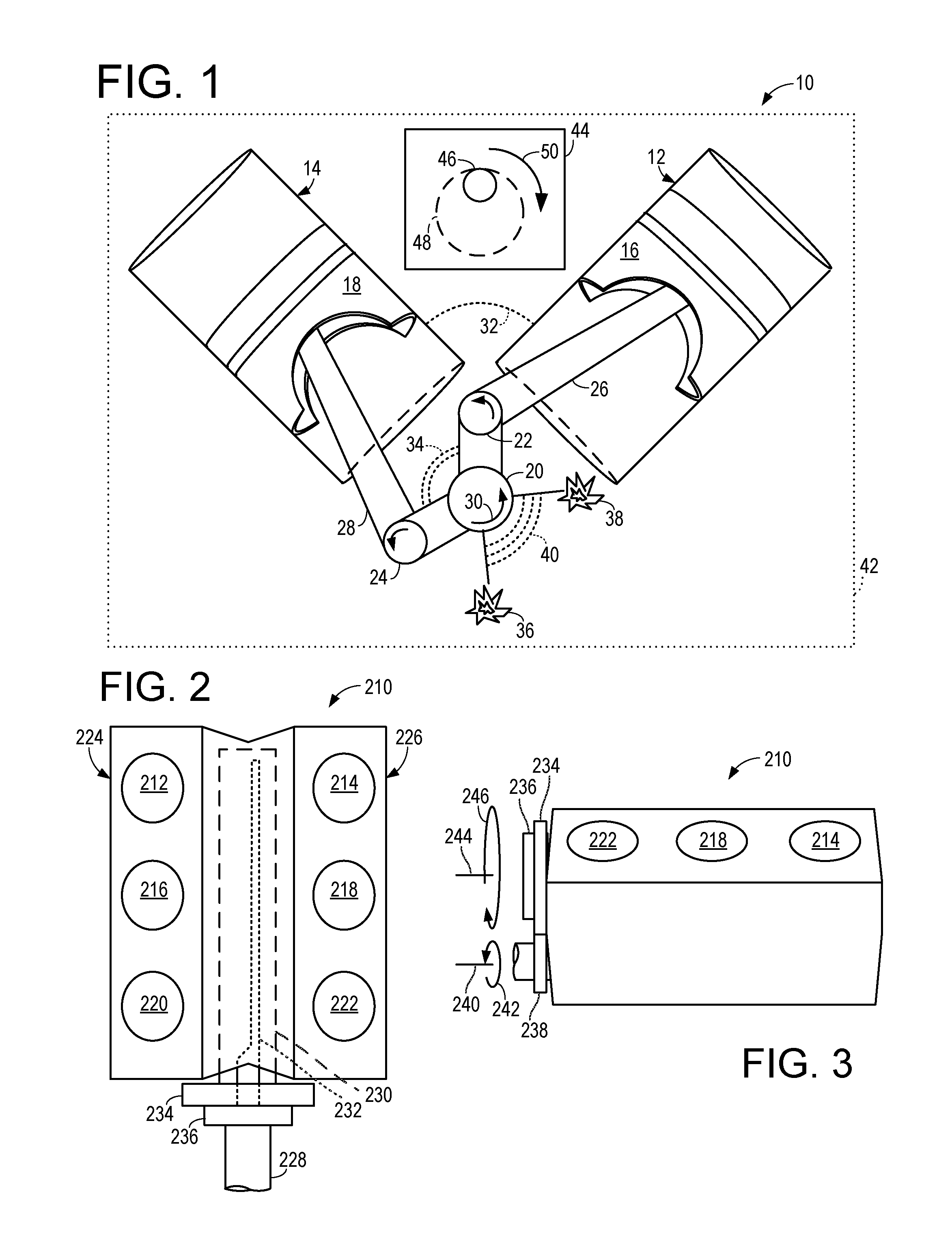
[0031]As one example, FIG. 1 shows aspects of an engine 10 (such as a diesel or gasoline engine) which may be included in a vehicle. Engine 10 may have a plurality of cylinders, including two cylinders, first cylinder 12 and second cylinder 14, each cylinder including a piston (16 and 18, respectively). Combustion of fuel within cylinder 12 drives first piston 16; likewise, combustion of fuel within second cylinder 14 drives second piston 18. Pistons 16 and 18 are coupled to a crankshaft 20 at first and second crank pins 22 and 24 via first and second connecting rods 26 and 28. In this way a cylinder (e.g., 12 or 14) may be coupled to the crankshaft 20 and drive the crankshaft 20 via combustion. Crankshaft 20 is shown begin driven in a first direction, one example of which is a counter-clockwise direction 30, about a first axis perpendicular to the page. Further examples of engine 10 include crankshaft 20 rotating in a clockwise direction.

[0032]Cylinders 12 and 14 may each be includ...


PUM


Abstract

The present application relates to a drive and balance mass. In one example, an engine includes, a camshaft, a balance shaft disposed within an interior of the camshaft, and a first gear, intermediate the balance shaft and the camshaft and driving the balance shaft to rotate about a first axis substantially parallel to a crankshaft of the engine in a direction opposite of the crankshaft. In another example, a balance mass and drive for an engine includes, a planetary gear set including a sun gear, a ring gear and a plurality of pinions mounted on a carrier, an input coupled to an input gear of the planetary gear set, a balance mass coupled to an output gear of the planetary gear set, the output gear configured to drive the balance mass to rotate about a first axis substantially parallel to the crankshaft in a direction opposite of the crankshaft.

Description

TECHNICAL FIELD[0001]The present application relates to a balance mass in an engine, and more particularly, to a drive for the balance mass in an engine.BACKGROUND AND SUMMARY[0002]The rotational motion of a crankshaft in an engine, along with additional connected mechanical parts such as crankpins, connecting rods and the like may produce unbalanced inertial moments and / or forces. These moments and / or forces may lead to undesirable noise vibration and harness for a vehicle operator.[0003]One approach to balancing the inertial moments and / or forces includes providing a balance shaft rotating along an axis parallel to the crankshaft, and in a direction opposite of the crankshaft. However, the inventors herein recognize various issues related to such an approach. Balance shafts may occupy significant space in an engine block, such as when placed in a valley of a “V” engine, in a cylinder head or in a sump of the engine block. Further, if a balance shaft is disposed in a camshaft, such...

Claims


Application Information

Patent Timeline
Patent Type & Authority Patents(United States)
IPC IPC(8): F02B75/06
CPCF02B75/06F16F15/264Y10T74/2184Y10T74/2183
Inventor MORGAN, PATRICK B.NOWACZYK, KENNETH L.
Owner FORD GLOBAL TECH LLC
Why Eureka
Try Eureka