
Method and system for detecting leakage of energy storage structure liquid

a technology of energy storage structure and liquid leakage, which is applied in the field of energy storage system, can solve the problems of electrolyte leakage through the wall into the battery case, electrolyte spewing, and electrolyte leakage, and achieve the effect of easy and rapid check and less resistan

Inactive Publication Date: 2012-07-03
THE UNITED STATES OF AMERICA AS REPRESENTED BY THE SECRETARY OF THE NAVY
View PDF5 Cites 12 Cited by
  • Summary
  • Abstract
  • Description
  • Claims
  • Application Information

AI Technical Summary

Benefits of technology

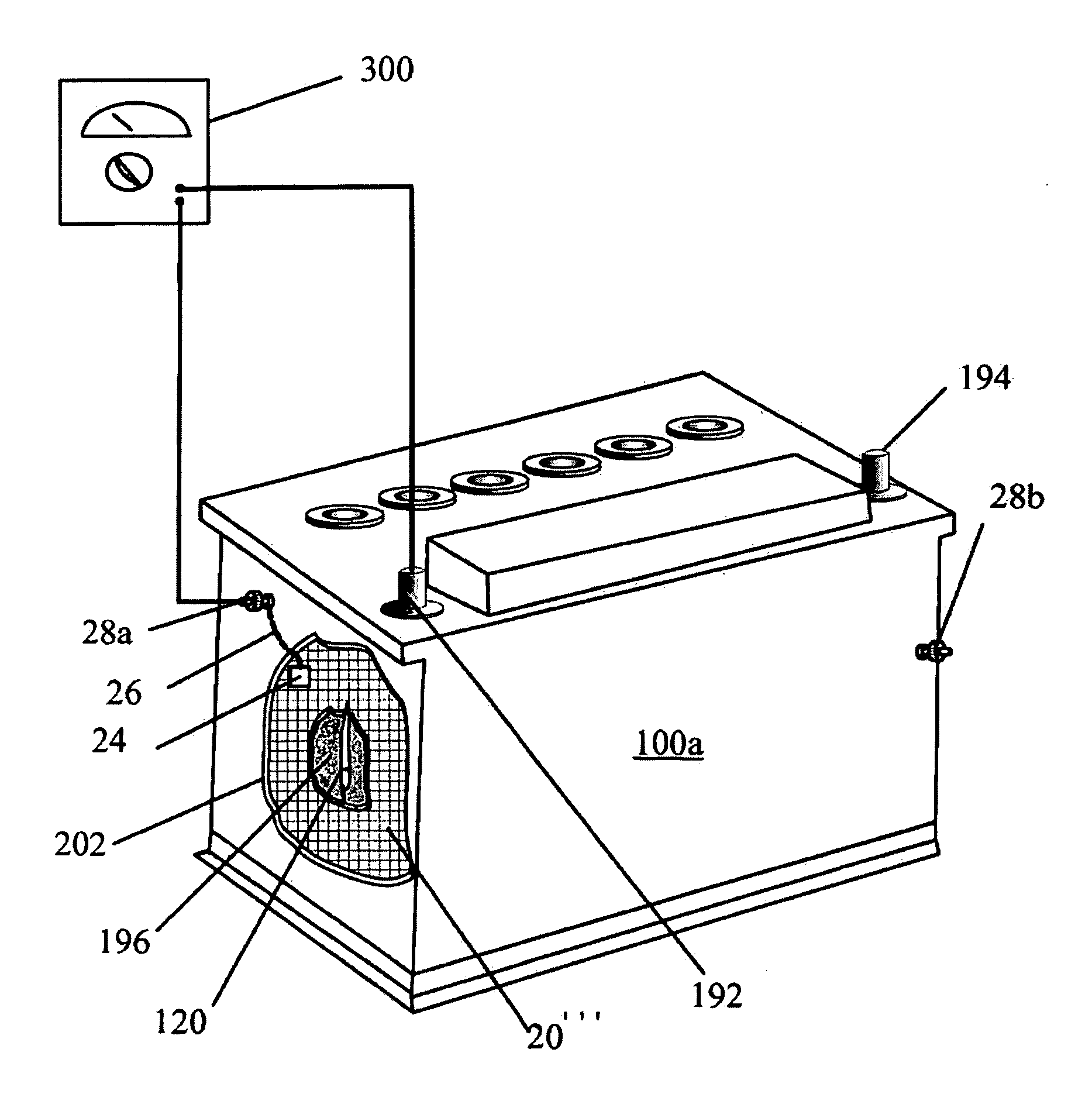
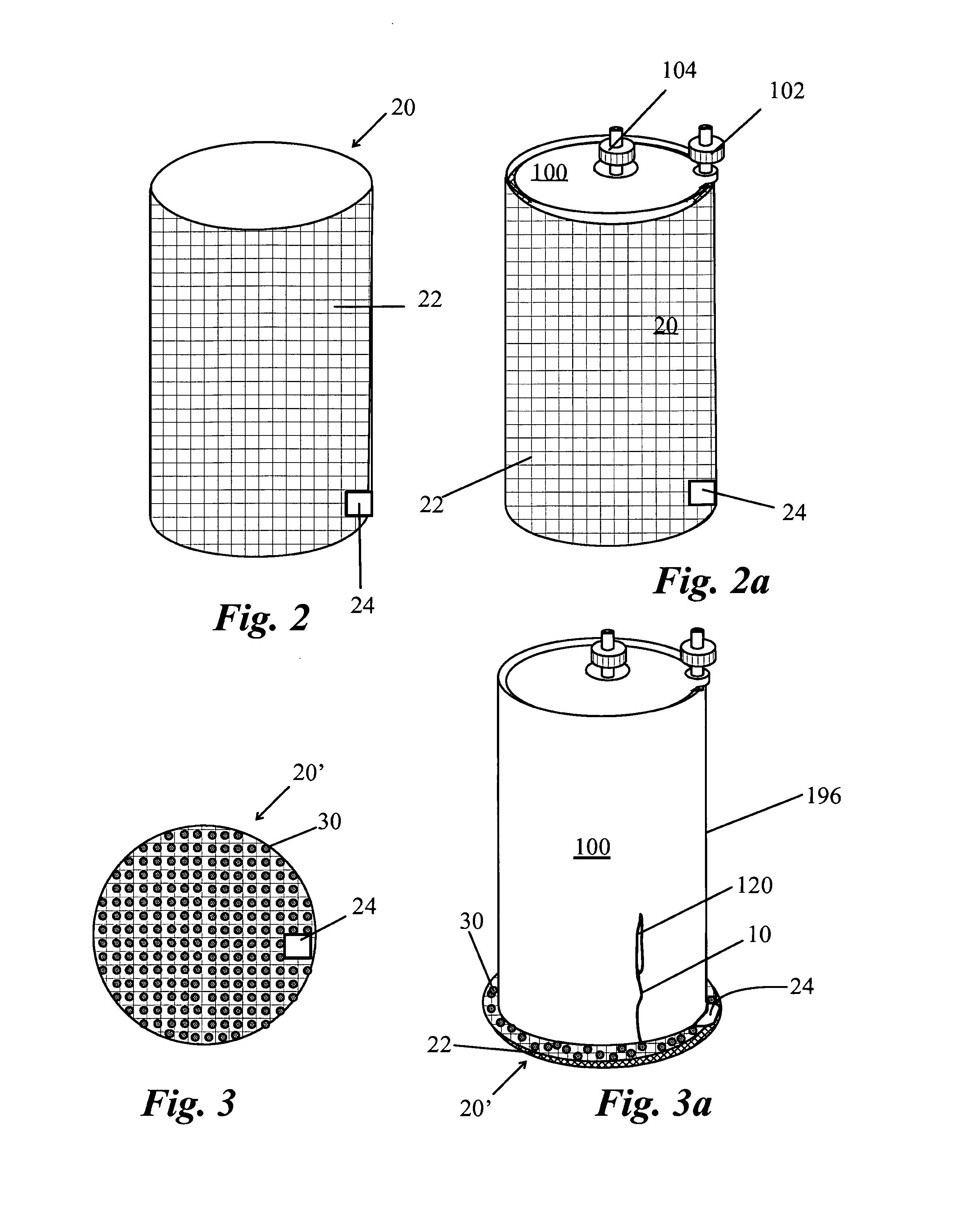
[0005]An embodiment of a method associated with the invention tests the conductivity between terminals coupled to each liquid permeable layer, and the method works irregardless of the electrical values or measurements of the battery case. The system is suited to easily and rapidly check for the presence of leaked electrolyte with the battery in place, and lends itself to automation and hierarchical network testing. This embodiment of the invention also potentially lends itself to determining the size of the breach, as the larger the opening the less resistance through the breach.

Problems solved by technology

Cracked cells or monoblocks cause electrolyte to leak through the wall into the battery case.
Electrolyte can also leak if the battery is overcharged, as the overcharging can cause the electrolyte to spew out of the cells or monoblocks.
Leaked electrolyte corrodes the battery case, and it is particularly corrosive to metal battery cases and the trays securing the battery, as well as adjacent equipment.

Method used


Image

  • Method and system for detecting leakage of energy storage structure liquid
  • Method and system for detecting leakage of energy storage structure liquid
  • Method and system for detecting leakage of energy storage structure liquid

Examples


Embodiment Construction

[0017]An electrolyte detection system and method is provided for a variety of battery types. If the battery has a conductive case, then the detection system typically requires a sensor with an insulating layer.

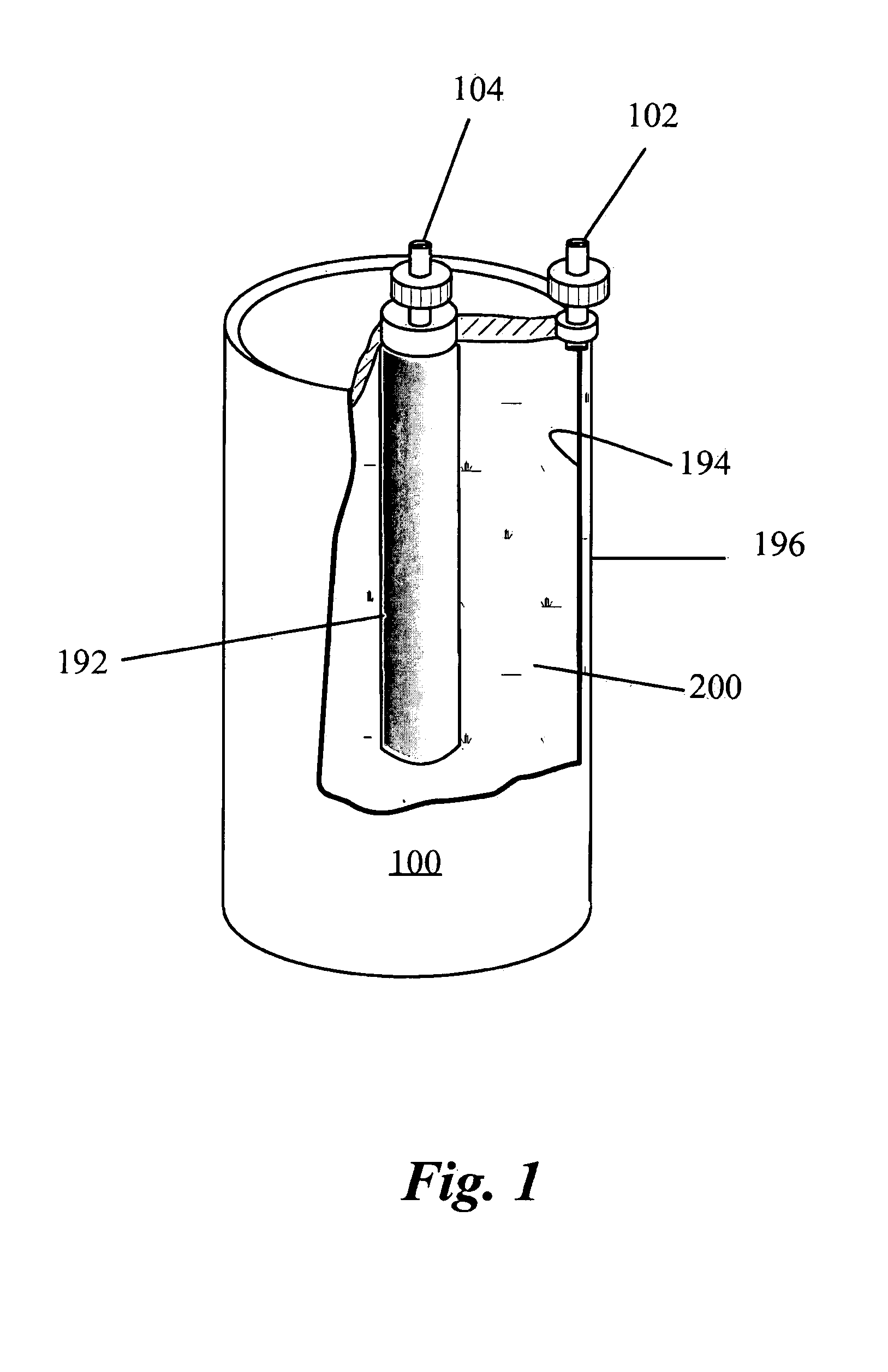
[0018]One example of a dry cell battery is shown in FIG. 1 having a cathode 192 with a positive terminal 104, an anode 194 with a negative terminal 102, an electrolyte 200 and an insular wall 196. In the illustrated battery 100, the anode 194 is a cylindrical layer of zinc, and the electrolyte 200 is typically a moist paste of ammonium chloride, zinc chloride and fillers. The cathode 192 can be carbon coated with manganese oxide. The insular wall 196 is comprised of a paper layer, and as the zinc is consumed the electrolyte moves closer and closer to the paper layer, and toward the end of the battery's life, it is common for the electrolyte to tear the wall and for electrolyte to leak out. It should be noted that an embodiment of the invention can be adapted for use with any t...


PUM

PropertyMeasurementUnit
electrical valueaaaaaaaaaa
electricalaaaaaaaaaa
electrical valuesaaaaaaaaaa

Abstract

A method and system for detecting liquid leaked from an energy storage structure, e.g., a battery is provided. One embodiment includes a sensor that detects the leaked electrolyte as it leaks through a breach in the wall retaining the electrolyte in the battery. The sensor has a sheet-like layer with a conductive surface and an electrical connection to a first interface. The sensor is positioned substantially flush to the battery wall, so that leaking electrolyte contacts the sensor. If the battery has a case, there is a first external communication point in electrical communication with the first interface. In the absence of leaked electrolyte there is substantially no electrical connection between the first external communication point and either of the terminals as indicated by a very high resistance. When leaked electrolyte is present there is an electrical connection between the first external communication point and either of the terminals.

Description

STATEMENT OF GOVERNMENT INTEREST[0001]The invention described herein was made in the performance of official duties by an employee of the Department of the Navy and may be manufactured, used, licensed by or for the United States Government for any governmental purpose without payment of any royalties thereon.FIELD OF THE INVENTION[0002]The present invention relates generally to energy storage systems, and more particularly to a system for detecting leakage of electrolyte from batteries.BACKGROUND[0003]Cracked cells or monoblocks cause electrolyte to leak through the wall into the battery case. Electrolyte can also leak if the battery is overcharged, as the overcharging can cause the electrolyte to spew out of the cells or monoblocks. Leaked electrolyte corrodes the battery case, and it is particularly corrosive to metal battery cases and the trays securing the battery, as well as adjacent equipment.SUMMARY OF THE INVENTION[0004]A method and system is provided for detecting liquid le...

Claims


Application Information

Patent Timeline
Patent Type & Authority Patents(United States)
IPC IPC(8): H01M10/48G01R27/00H01M2/02H01M50/569
CPCH01M10/48H01M10/484H01M10/482Y02E60/10H01M50/569
Inventor WAGGONER, SUSAN MARIE
Owner THE UNITED STATES OF AMERICA AS REPRESENTED BY THE SECRETARY OF THE NAVY
Learn More