Procedures and control system to control a brushless electric motor

a technology of electric motors and control systems, applied in the direction of motor/generator/converter stoppers, dynamo-electric converter control, instruments, etc., can solve the problems of short lifetime, large overall size, and extra cost due to the addition of controllable semiconductors

Active Publication Date: 2012-07-03
EBM PAPST MULFINGEN GMBH & CO KG
View PDF5 Cites 18 Cited by
  • Summary
  • Abstract
  • Description
  • Claims
  • Application Information

AI Technical Summary

Benefits of technology

[0017]According to the invention the pulsating DC voltage, i.e. a voltage that is not constant over time, that was initially generated by rectifying the line AC voltage is dynamically increased with respect to its instantaneous values using a step-up chopper in such a manner that the resulting DC link voltage with reduced ripple always lies above a defined limit voltage over time. The voltage that is sufficient for the respective electric motor to be always able to impress a motor current onto the windings via the inverter over the entire phase curve is specified as the limit voltage. With a suitable design of the step-up chopper and its controller, a nearly constant DC voltage can advantageously be generated from the strongly pulsating DC voltage. For this purpose, the pulsating DC voltage is connected to an inductor at a pulse duty ratio regulated on the basis of the respective current DC link voltage, and added up via a freewheeling diode and a DC link capacitor downstream of the inductor. A simple and inexpensive film capacitor of the order of only a few μF is sufficient for the DC link capacitor.
[0019]A control system according to the invention first of all consists of the ordinary components of an EC controller, specifically a network rectifier and an inverter connected downstream via a DC link that is used to generate quasi-sinusoidal motor currents for a corresponding voltage clocking (modulation) of a PWM controller. According to the invention, the control system has an integrated step-up chopper with a controller designed in such a manner that, in terms of the method according to the present invention, a pulsating DC voltage rectified by the network rectifier is dynamically increased relative to its instantaneous values in such a manner that a resulting DC link voltage with reduced ripple always lies above a defined limit voltage over time. The step-up chopper has an inductor in series with a freewheeling diode and a downstream DC link capacitor, wherein the inductor is clocked with a pulsating DC voltage via a controllable electronic switch. The electronic switch for clocking the inductor is driven with pulse width modulation by a voltage regulator with variable clock frequency, specifically as a function of the respective current DC link voltage and a predetermined limit voltage. The controller activates the step-up chopper only in the phases of commutation in which all windings of the electric motor are short-circuited. In that way, the stray inductances of the motor winding heads can be used as the inductor for the step-up chopper.
[0020]The stray winding head inductances used according to the invention for the step-up chopper inductance depend, with respect to the size of their effective inductance, on the design of the respective electric motor or its stator and its stator windings. In an advantageous refinement of the invention, however, the stray inductances of the motor winding heads can be influenced, specifically, reduced or increased, by additional measures with respect to their effective inductance. For this purpose, magnetically active means with higher or lower magnetic permeability can be provided at least on one axial side of the motor or stator in order to influence the actually existing air gap permeability and the magnetic flux leakage. Some concrete examples of these measures will be described in more detail below.

Problems solved by technology

In practical use, the latter have certain disadvantages, however, particularly a large overall size and a short lifetime.
Problems appear with this “slim DC link” technology, especially in case of a supply from a single phase line, since the rectified DC voltage pulsates very strongly at a frequency of, for example, 100 Hz with a voltage curve corresponding to the sinusoidal line AC voltage.
The disadvantage in this case is that the motor currents have to be detected to accomplish this, and that an excessively fast current regulation can induce a system consisting of a system inductance and a DC link capacitor to oscillate.
The disadvantage of this in principle well-functioning arrangement is the extra cost due to the additional controllable semiconductors, which becomes noticeable particularly in large series production.

Method used


Image

  • Procedures and control system to control a brushless electric motor
  • Procedures and control system to control a brushless electric motor
  • Procedures and control system to control a brushless electric motor

Examples


Embodiment Construction

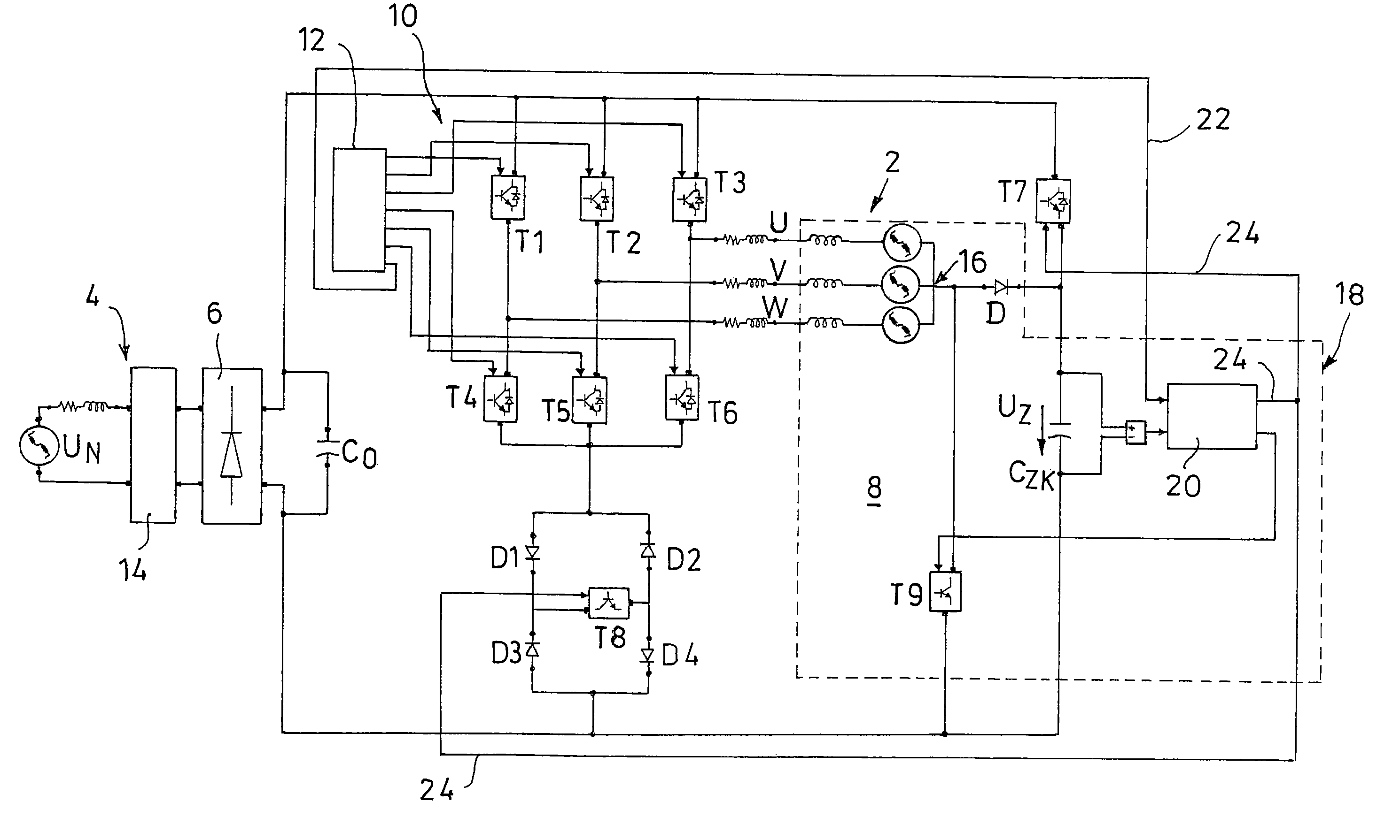
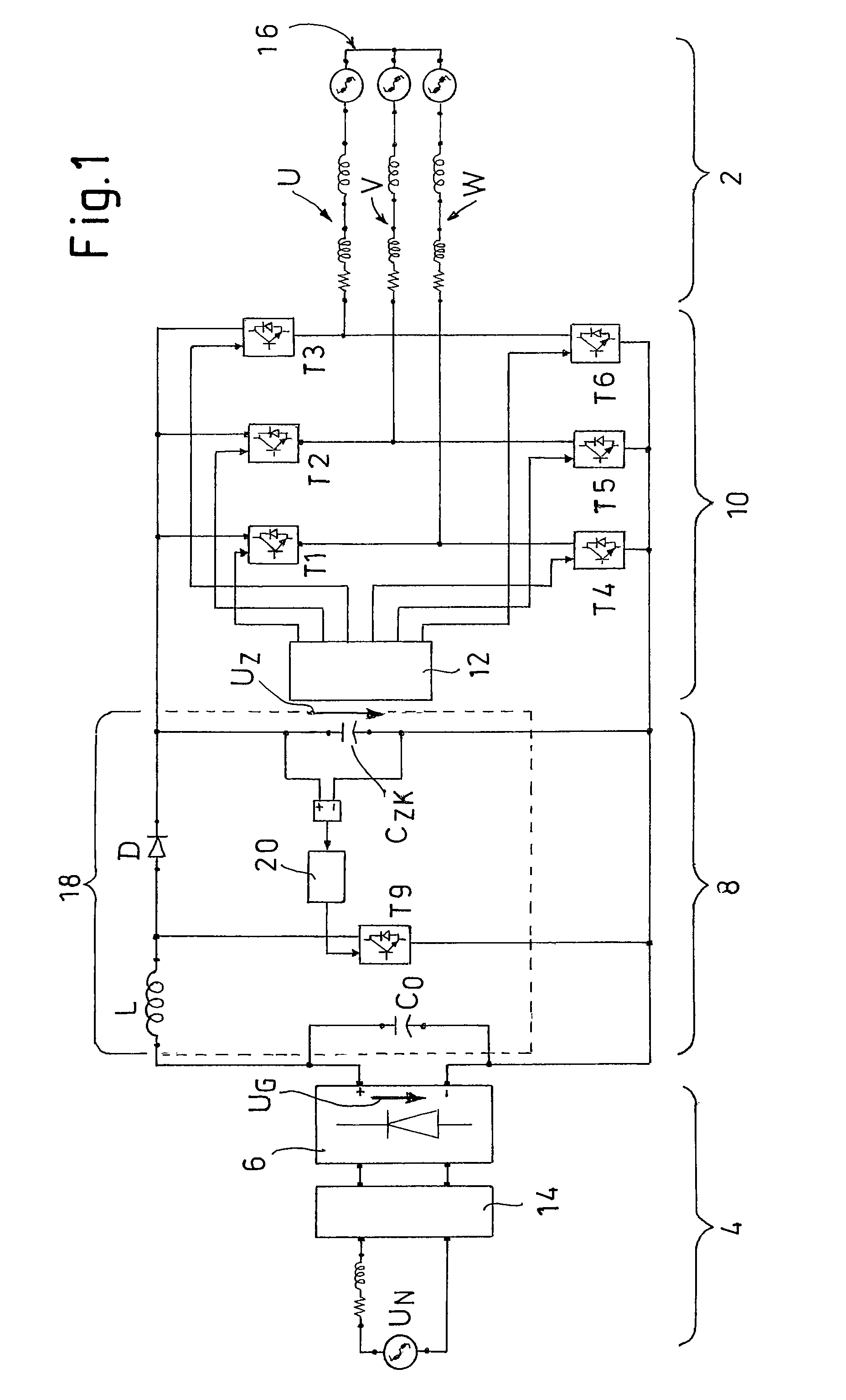
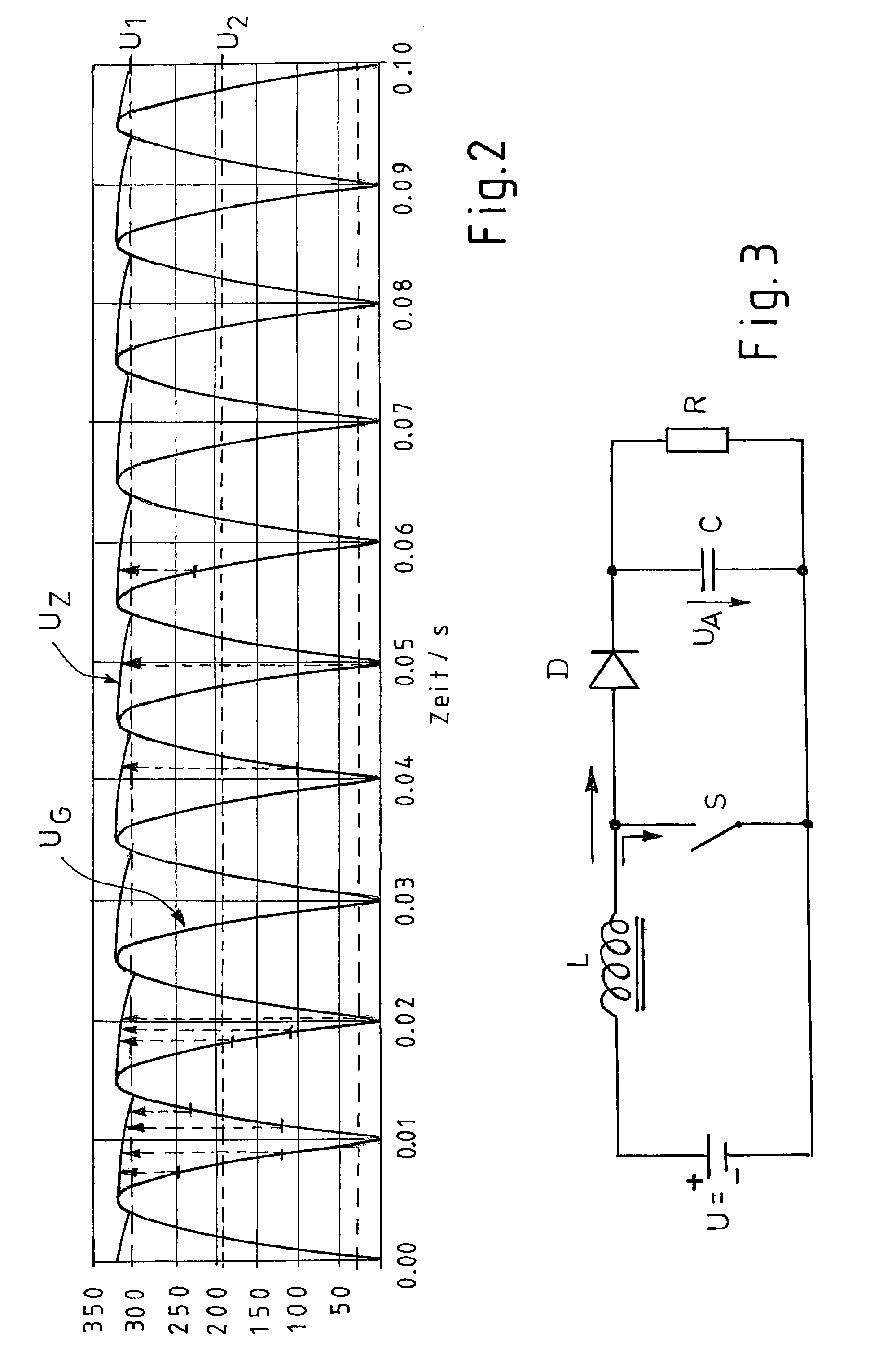
[0047]As follows from FIG. 1, a control system for driving a collectorless electronically commutated electric motor (EC-PMSM=electronically commutated permanent magnet excited synchronous motor) consists of a line voltage supply 4 that rectifies a line AC voltage UN via a network rectifier 6 into a pulsating DC voltage UG (cf. the diagram in FIG. 2). Via a DC link 8, the line voltage supply 4 feeds a controlled inverter 10 (power output stage), which is controlled in a known manner by a control unit 12 for supplying and commutating and, in particular, also for adjusting the speed of the motor 2.

[0048]A line filter 14 in the vicinity of the line voltage supply 4 that reduces high-frequency current oscillations, and thus improves the electromagnetic compatibility (EMV), is drawn in FIG. 1. Only three stator windings U, V, W of the, preferably three-strand, electric motor 2 are shown in an equivalent circuit representation, a star connection with a shared star point 16 being provided i...


PUM


Abstract

The present invention relates to a method and a control system for driving a three-strand brushless, electronically commutated electric motor (2), wherein a line AC voltage (UN) is rectified and fed via a slim DC link (8) with minimum DC link reactance as a DC link voltage (UZ) to an inverter (10) that can be driven to supply and commutate the electric motor (2). A pulsating DC voltage (UG) initially generated by rectifying the line AC voltage (UN) is dynamically increased with respect to its instantaneous values by a step-up chopper (18) in such a manner that the resulting DC link voltage (UZ) with a reduced ripple always lies above a defined limit voltage (U18 / U1) over time. The control system consists of a network rectifier (6), a downstream slim DC link (8) with minimum DC link reactance and a controllable inverter (10) that can be supplied via the DC link and driven to commutate the electric motor (2). A step-up chopper (18) is integrated therein with a controller (20) designed in such a manner that, the pulsating DC voltage (UG) rectified by the network rectifier (6) is dynamically increased with respect to its instantaneous values in such a manner that the resulting DC link voltage (UZ) with a reduced ripple always lies above a defined limit voltage (U20 / U1) over time. Stray inductances (Ls1-Ls3) of the motor winding heads present in the electric motor (2) are used as inductor (L) for the step-up chopper (18).

Description

CROSS REFERENCE TO RELATED APPLICATIONS[0001]This application claims priority to European patent application number 09163651.4, filed Jun. 4, 2009 and European patent application number 10166480.3, filed Jun. 18, 2010.FIELD OF THE INVENTION[0002]The present invention first relates to a method for driving a brushless, electronically commutated electric motor, a three-strand motor in particular, wherein an AC line voltage is rectified and fed via a slim DC link with minimum DC link reactance as a DC link voltage to an inverter that can be driven to supply and commutate the electric motor.[0003]The invention further relates to a corresponding control system using, in particular, the method of the invention, with a network rectifier, a downstream slim DC link with minimum DC link reactance, and a controllable inverter that can be supplied via the DC link and driven to commutate the electric motor.BACKGROUND OF THE INVENTION[0004]Electronically commutated motors, known as EC motors, are ...

Claims


Application Information

Patent Timeline
Patent Type & Authority Patents(United States)
IPC IPC(8): H02P27/00
CPCH02P6/001H02P6/085H02P25/026H02M2001/007H02P2209/01H02P2201/09H02P2201/15H02P6/34H02P25/03H02M1/007
Inventor WYSTUP, RALPHLIPP, HELMUT
Owner EBM PAPST MULFINGEN GMBH & CO KG
Why Eureka
Try Eureka