Image forming apparatus provided with transfer roller

a technology of transfer roller and forming apparatus, which is applied in the direction of electrographic process apparatus, instruments, optics, etc., can solve the problems of large resistance variation in the use environment (temperature and humidity), abraded transfer roller, and increased resistance, so as to prevent the formation of black dots and suppress jitter and density unevenness

Inactive Publication Date: 2012-07-03
KYOCERA DOCUMENT SOLUTIONS INC
View PDF7 Cites 4 Cited by
  • Summary
  • Abstract
  • Description
  • Claims
  • Application Information

AI Technical Summary

Benefits of technology

[0017]An object of the present invention is to provide an image forming apparatus capable of preventing the formation of black dots caused by the destruction of a photoconductive layer outside the widthwise edge portions of a sheet and suppressing jitter and density unevenness caused by the vibration of a transfer roller.

Problems solved by technology

On the other hand, in a transfer roller of the ion conductive type, there are problems that a resistance variation in a use environment (temperature and humidity) is large and resistance increases due to the application of a large current of a transfer bias.
If the rubber of the transfer roller has a low hardness, the transfer roller may be abraded after a long-term use and, in such a case, problems such as a skew, a magnification defect and a transfer deviation may possibly occur.
Thus, the transfer roller is likely to vibrate and to be separated from the photoconductive drum due to this vibration, for example, if transfer press is set to be low or frictional forces between the transfer roller and the photoconductor or the transfer medium are large.
A first problem of the above construction is as follows.
This results from the inability of rubber elasticity to follow the air gaps due to the high rubber hardness of the transfer roller.
Thus, there are cases where the surface of the photoconductor is destroyed and black dots appear in a transferred image in long-term use.
If the transfer press is excessively increased, problems such as polishing nonuniformity of the surface of the photoconductive drum 7 and a hollow phenomenon at the time of passing a thick sheet occur.
Accordingly, it is difficult to prevent the vibration of the transfer roller only by the transfer load setting.
In this case, a voltage to be discharged in a clearance increases in a state of a large transfer bias output and if this voltage exceeds a withstanding voltage of the drum, a photoconductive layer is destroyed.
As a result, electric charges can be no longer retained on the surface of the photoconductor, whereby black dots appear in an image.

Method used


Image

  • Image forming apparatus provided with transfer roller
  • Image forming apparatus provided with transfer roller
  • Image forming apparatus provided with transfer roller

Examples


first embodiment

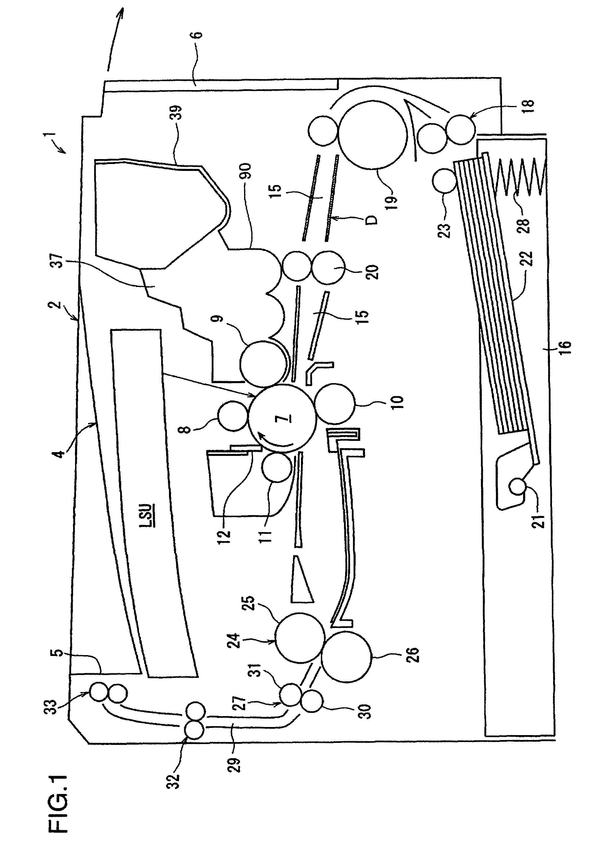
[0028]An image forming apparatus according to the present invention is described with reference to the accompanying drawings. With reference to FIG. 1, a laser printer 1 (hereinafter, referred to merely as the “printer 1”) as an example of the image forming apparatus includes a printer main body 2 having a substantially rectangular parallelepipedic housing structure. Right side of the printer main body 2 in FIG. 1 is referred to as front side of the apparatus.

[0029]A sheet cassette 16 is arranged at the bottom of the printer main body 2. A bottom plate 22 as a sheet placing plate having one end thereof supported rotatably about a shaft 21, a compression coil spring 28 for pushing up the other end of the bottom plate 22, etc. are arranged in the sheet cassette 16. The upper surface of the leading end of the uppermost one of sheets stacked and accommodated on the bottom plate 22 is pressed in contact with a pickup roller 23 arranged in the printer main body 2. The pickup roller 23 fun...

second embodiment

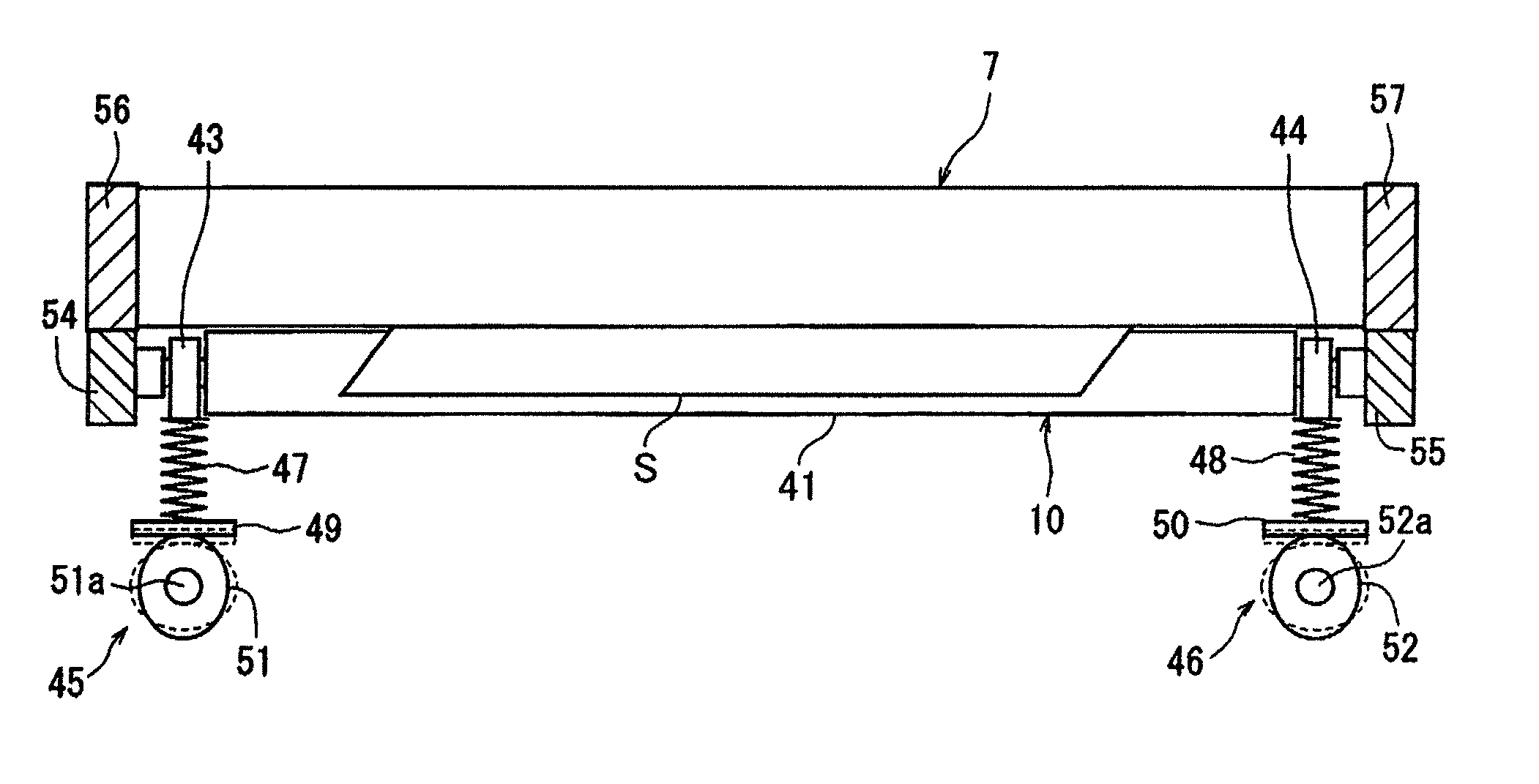
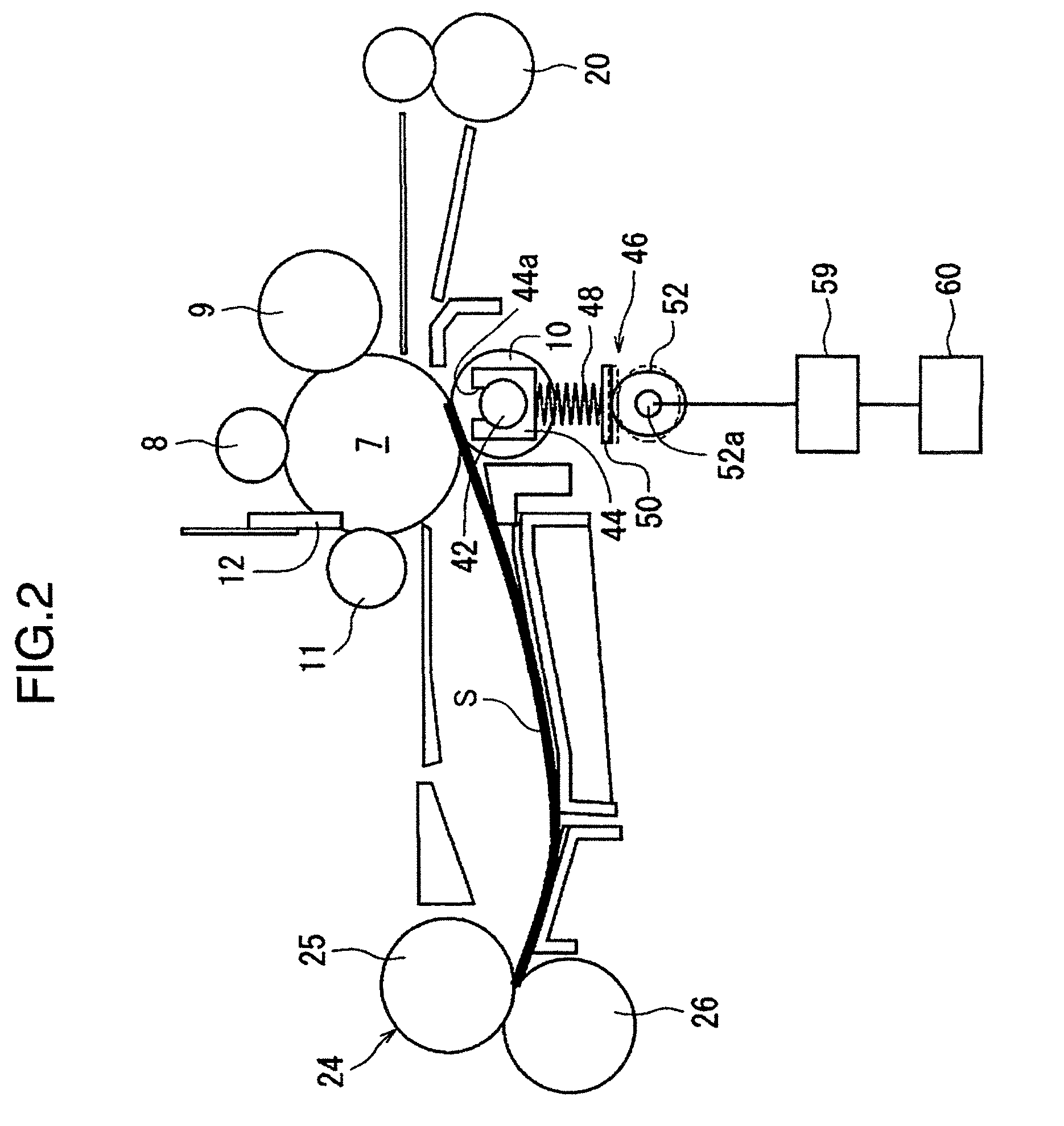
[0071]Next, functions of the image forming apparatus 1 in the second embodiment are described. For example, a case is assumed where printing is performed using an A4-size sheet accommodated in the cassette 16 in the printer 1 shown in FIG. 1. A print signal for A4 size is transmitted from a personal computer to the controller 60 of the printer 1 by a user to input sheet information in the controller 60 of the printer main body 2. Here, if the biasing force changing mechanisms 45, 46 are set for the small size and are not so set as to give biasing forces suitable for the A4 size as the large size to the transfer roller 10, the controller 60 controls the mechanism unit 59 to set the eccentric cams 51, 52 at positions suitable for the A4 size.

[0072]Specifically, if the biasing force changing mechanisms 45, 46 are set for the B5 size, the controller 60 rotates the eccentric cams 51, 52 to narrow the distances between the roller bearings 43, 44 and operation plates 49, 50 to set the ecce...

third embodiment

[0088]Next, functions of the image forming apparatus 1 in the third embodiment are described. For example, a case is assumed where printing is performed using an A4-size sheet accommodated in the cassette 16 in the printer 1 shown in FIG. 1. A print signal for A4 size is transmitted from a personal computer to the controller 60 of the printer 1 by a user to input sheet information in the controller 60 of the printer main body 2. Here, if the biasing force changing mechanisms 45, 46 are not so set as to give biasing forces suitable for the A4 size as the large size to the transfer roller 10, the controller 60 controls the mechanism unit 59 to set eccentric cams 51, 52 at positions suitable for the A4 size.

[0089]Specifically, if the biasing force changing mechanisms 45, 46 are set for the B5 size, the controller 60 rotates the eccentric cams 51, 52 to narrow the distances between the roller bearings 43, 44 and operation plates 49, 50 to set the eccentric cams 51, 52 at the positions s...


PUM


Abstract

An image forming apparatus has an image bearing member on which a toner image is to be formed. A transfer roller contacts a surface of the image bearing member for transferring a toner image on the image bearing member to one side of a transfer medium by applying a voltage having a polarity opposite to that of the toner image on the image bearing member from the other side of the transfer medium. A biasing member biases the transfer roller toward the image bearing member. The transfer roller is shaped such that the outer diameter of a first part corresponding to the width of a specified sheet size is constant and the outer diameters of second parts located closer to opposite ends of the transfer roller than the first part are gradually increased toward the outer sides in an axial direction.

Description

BACKGROUND OF THE INVENTION[0001]1. Field of the Invention[0002]The present invention relates to an image forming apparatus with an improved print quality such as a copier, a printer, a facsimile machine or a complex machine of these.[0003]2. Description of the Related Art[0004]Conventionally, there has been known the following electrophotographic image forming apparatus. An electrostatic latent image is formed by exposing a surface of a photoconductive drum including a photoconductive layer made of OPC, amorphous silicon or the like and uniformly charged by a charger with light from a laser, an LED or the like in accordance with image information. This electrostatic latent image is developed into a toner image by a developing unit and this toner image is transferred to a transfer medium (sheet) by a transfer unit. The transfer medium is separated from the photoconductive drum by a separator and the toner image on the transfer medium is fixed to the transfer medium by a fixing devic...

Claims


Application Information

Patent Timeline
Patent Type & Authority Patents(United States)
IPC IPC(8): G03G15/00
CPCG03G15/167
Inventor OKAMOTO, SUEAKI
Owner KYOCERA DOCUMENT SOLUTIONS INC
Why Eureka
Try Eureka