Appliance latch with power failure unlock

a technology of power failure and latch, which is applied in the direction of wing accessories, cleaning using liquids, and separation processes, etc., can solve the problems of preventing rapid locking or unlocking of the locking mechanism, requiring a heating or cooling of a material, and requiring a long heating or cooling process, so as to improve the cost and power consumption quality, and the effect of quick locking and unlocking of the appliance door

Active Publication Date: 2012-07-10
ILLINOIS TOOL WORKS INC
View PDF14 Cites 9 Cited by
  • Summary
  • Abstract
  • Description
  • Claims
  • Application Information

AI Technical Summary

Benefits of technology

[0009]The present invention provides latching mechanism that employs a bi-stable solenoid for rapid locking and unlocking of an appliance door while storing energy to unlock the appliance door in the event of power failure in a separate thermal actuator. The thermal actuator may have improved costs and power consumption qualities over a continuous duty solenoid.
[0010]Specifically, the present invention provides a door locking assembly for use in an appliance receiving electrical power from a power line and having a door that may be opened to provide access to a wash chamber. The door locking assembly includes a bi-stable electromagnetic locking mechanism which, in a locked state, holds the door closed until an electrical unlock signal is received and, in an unlocked state, allows the door to be freely opened until an electrical lock signal is received. The electromagnetic locking mechanism is capable of remaining stably in the locked state or unlocked state absent application of the electrical unlock signal or the electrical lock signal. A thermal actuator communicates with the bi-stable electromagnetic locking mechanism to: (1) store energy while the power line provides electrical power, (2) use the stored energy to unlock the bi-stable electromagnetic locking mechanism when the bi-stable electromagnetic locking mechanism is in a locked state and power is lost at the power line, and (3) provide a time delay period, to allow the appliance to come to a standstill, before the thermal actuator cools to a point where an unlock status is initiated.
[0011]Thus it is an object of one embodiment of the invention to provide the high-speed and low power consumption of a bi-stable actuator while preventing a lockout in the event of power failure.

Problems solved by technology

Such thermal actuators have the disadvantage of requiring a heating or cooling of a material.
This heating or cooling process typically takes some time, preventing rapid locking or unlocking of the locking mechanism.
Electrical solenoids provide for rapid actuation but at a cost of increased size and expense, particularly if the coil windings, the latter of which normally must be rated for continuous duty to maintain the locking mechanism in its locked or unlocked state.
The use of continuous duty solenoids in locks can also create a problem in the event of a electrical power loss, caused either by an electrical outage, or the appliance being unplugged, where the end user will have access to the inside of the washer while the drum is still spinning.
In the event of a loss of electrical power, the door latch may be locked indefinitely because no power is available to move the bi-stable solenoid to its unlocked state.
This is an important problem in commercial laundry establishments where, in the event of power failure, customers will not be able to collect their clothes and yet may be reluctant to leave their clothes unattended.
This approach, while extremely flexible, requires an additional electrical circuit and a capacitor sized to store sufficient energy, which can be expensive.

Method used


Image

  • Appliance latch with power failure unlock
  • Appliance latch with power failure unlock
  • Appliance latch with power failure unlock

Examples


Embodiment Construction

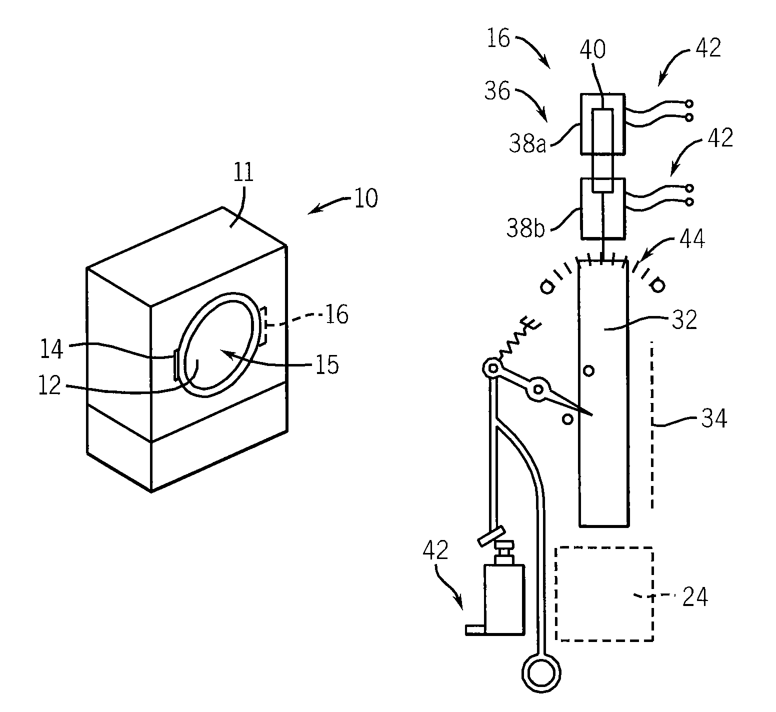
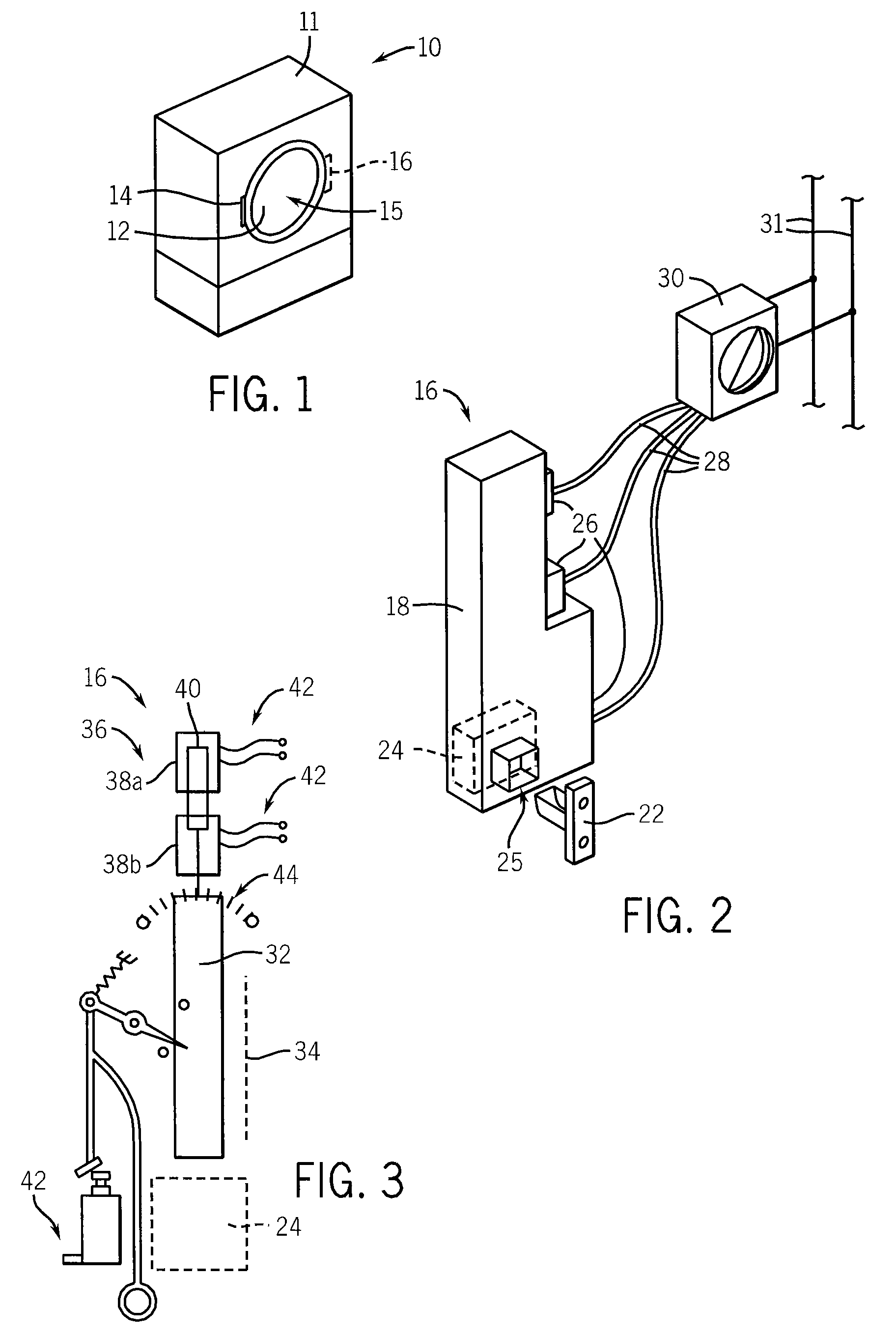
[0044]Referring now to FIG. 1, a front loading washing machine 10 may provide a cabinet 11, having at its front surface a door 12, the latter opening about a hinge 14 between an open and closed position to provide access to a washing chamber 15. The door 12 may be retained in the closed position (as shown) by a door locking assembly 16 having components within the cabinet 11 and attached to a rear face of the door 12.

[0045]Referring now also to FIG. 2, the door locking assembly 16 may provide a housing 18 with an opening 25, a similar opening in the front surface of the cabinet 11 to receive a latch tongue 22 attached to the rear side of the door 12. The latch tongue 22 is releasably held by a latching assembly 24 within the housing 18. A latching assembly 24 suitable for this purpose is described in co-pending U.S. application Ser. No. 11 / 071,910 entitled: “Appliance Latch Having a Rotating Latch Hook Mounted on a Linear Slide” and U.S. patent application Ser. No. 11 / 684,287 entitl...


PUM

PropertyMeasurementUnit
electrical poweraaaaaaaaaa
store energyaaaaaaaaaa
stored energyaaaaaaaaaa

Abstract

A lock for a washing machine or the like provides fast actuation through a solenoid driven bolt that remains stably in the locked position after power is no longer applied to the solenoid. The possibility of power failure preventing subsequent access to the washing machine is avoided through the use of a slower actuation time, thermal actuator storing sufficient energy to unlock the bolt after a time delay when power is lost.

Description

CROSS-REFERENCE TO RELATED APPLICATIONS[0001]This application claims the benefit of U.S. Provisional Application 60 / 925,597, filed Apr. 20, 2007, the disclosure of which is incorporated herein by reference.STATEMENT REGARDING FEDERALLY SPONSORED RESEARCH OR DEVELOPMENT--BACKGROUND OF THE INVENTION[0002]The present invention relates to latching mechanisms for the doors of appliances such as clothes washing machines and, in particular, to an electrically actuated lock for such latching mechanisms.[0003]Appliances, such as clothes washing machines and dishwashers, may operate automatically through one or more cycles under the control of a timer. During cycles when the consumer might be exposed to spraying water or hazardous moving parts, the door to the appliance may be locked by an electrical signal from the timer. The locking mechanism may, for example, insert a blocking member into a portion of the door latch to prevent the latch from opening, or the locking mechanism may insert a b...

Claims


Application Information

Patent Timeline
Patent Type & Authority Patents(United States)
IPC IPC(8): D06F33/02D06F37/42E05F15/60
CPCD06F37/42D06F39/14Y10T70/713
Inventor HAPKE, KENYON A.OSVATIC, MICHAEL S.
Owner ILLINOIS TOOL WORKS INC
Why Eureka
Try Eureka