Device for actuating a gearwheel, which is designed as a loose wheel, of a transmission device

a gearwheel and gearwheel technology, applied in mechanical devices, gearwheels, transportation and packaging, etc., can solve the problems of increasing the actuation force, attempting to actuate from the inside of the transmission shaft outward, etc., to achieve the effect of reducing the need for structural space, reducing the cost and complexity of sealing, and small demand for structural spa

Active Publication Date: 2012-07-10
ZF FRIEDRICHSHAFEN AG
View PDF15 Cites 2 Cited by
  • Summary
  • Abstract
  • Description
  • Claims
  • Application Information

AI Technical Summary

Benefits of technology

[0016]A device made with an actuator of such type is of compact and lightweight structure, and compared with designs known from the prior art for connecting gearwheels in a rotationally fixed manner to a shaft of a transmission device, it is characterized by little demand for structural space because the actuator is accommodated completely inside the shaft.
[0017]In addition, compared with the known systems the cost and complexity of sealing is reduced with the device according to the invention, since the entire piston-cylinder unit is connected rotationally fixed to the shaft carrying the loose wheel, and there is no need for drive decoupling means in the area of an active connection between the actuator and preferably a shift element that actuates the loose wheel, which is usually also connected in a rotationally fixed manner to the shaft. Accordingly, piston spaces of the piston-cylinder unit that are to be acted upon by pressure medium involve no relative rotary movements between a cylinder and a piston which delimit the piston spaces of the piston-cylinder unit, and sealing is only necessary in relation to translational relative movements between the cylinder and the piston.
[0019]Thus, the actuator of the device for actuating a gearwheel of a transmission device made as a loose wheel is arranged inside the shaft in a space-saving manner, so that compared with conventional transmission devices such a transmission device can be made with smaller structural space dimensions.
[0020]Furthermore the embodiment according to the invention of the device as described is characterized by low sealing cost and complexity, since the drive decoupling means between the actuator and the components provided for actuating the gearwheel have been moved away from the parts of the actuator acted upon by pressure medium, to an essentially pressure-free zone. The result is that in a simple manner, the actuation forces for engaging or disengaging a gearwheel are not increased to an undesired extent by friction forces caused by contact seals.
[0021]The device according to the invention for actuating a gearwheel of a transmission device made as a loose wheel, is also characterized by small demand for structural space, again because the actuator, preferably in the form of a pneumatic or hydraulic motor connected in a rotationally fixed manner relative to the shaft, is completely accommodated inside the shaft.
[0022]In addition, in the same manner as the design of the device according to the invention described above, the design of the device, in which the motor is fixed on the housing or rotationally fixed relative to the shaft, is located, in the area of the active connection between an output shaft of the motor and the gearwheel to be actuated or between the motor output shaft and the shaft, in an unpressurized zone with drive decoupling means, so that compared with systems known from the prior art the sealing complexity is reduced and the gearwheel can be changed from an engaged or disengaged condition to a disengaged or engaged condition by actuation forces as small as possible.

Problems solved by technology

The hydraulic actuation of the shift sleeve provided for fixing the gearwheels made as loose wheels requires, in the axial extension of the shaft, structural space between gearwheels arranged on the shaft and to be actuated, and because of this the reduction of the need for structural space, attempted by actuating from the inside of a transmission shaft outward, is not achieved to the desired extent.
In addition, a piston space associated with the shift sleeve is disadvantageously sealed relative to its surroundings by so-termed contact sealing devices, so that during the movement of the piston relative to the cylinder undesirably large friction forces are produced because of the sometimes high actuation pressures.
In turn these friction forces lead to an increase of the actuation forces that have to be applied to actuate the piston.
Moreover, the sealing action of a contact seal deteriorates with increasing operating time because of friction, and in some circumstances this compromises the functionality of such control means.
In addition, further friction losses occur in the area of lubrication oil inlets provided between a housing and the transmission shaft, for the reasons already stated these are undesired.
Disadvantageously, it is very elaborate and expensive to seal and mount such an oil supply unit relative to its surroundings, and the oil supply unit must be arranged coaxially with respect to the shaft.
Owing to the high relative rotational speeds that occur during the operation of a transmission device, between a piston connected to the connection rod and the cylinder housing, either complex and costly sealing of the piston space delimited by the piston and the cylinder housing is necessary, this being affected by friction and wear, or the piston space will be characterized by substantial amounts of leakage that cause large pressure and oil losses.
The disadvantage here, however, is that the drive decoupling between the connection rod and the cylinder housing is achieved by a corresponding connection between a piston and the connection rod, for example a slide or roller bearing, and the seal between the piston spaces separated from one another by the piston, which is necessary for proper functionality, is achieved only with considerable cost and complexity.

Method used


Image

  • Device for actuating a gearwheel, which is designed as a loose wheel, of a transmission device
  • Device for actuating a gearwheel, which is designed as a loose wheel, of a transmission device
  • Device for actuating a gearwheel, which is designed as a loose wheel, of a transmission device

Examples


Embodiment Construction

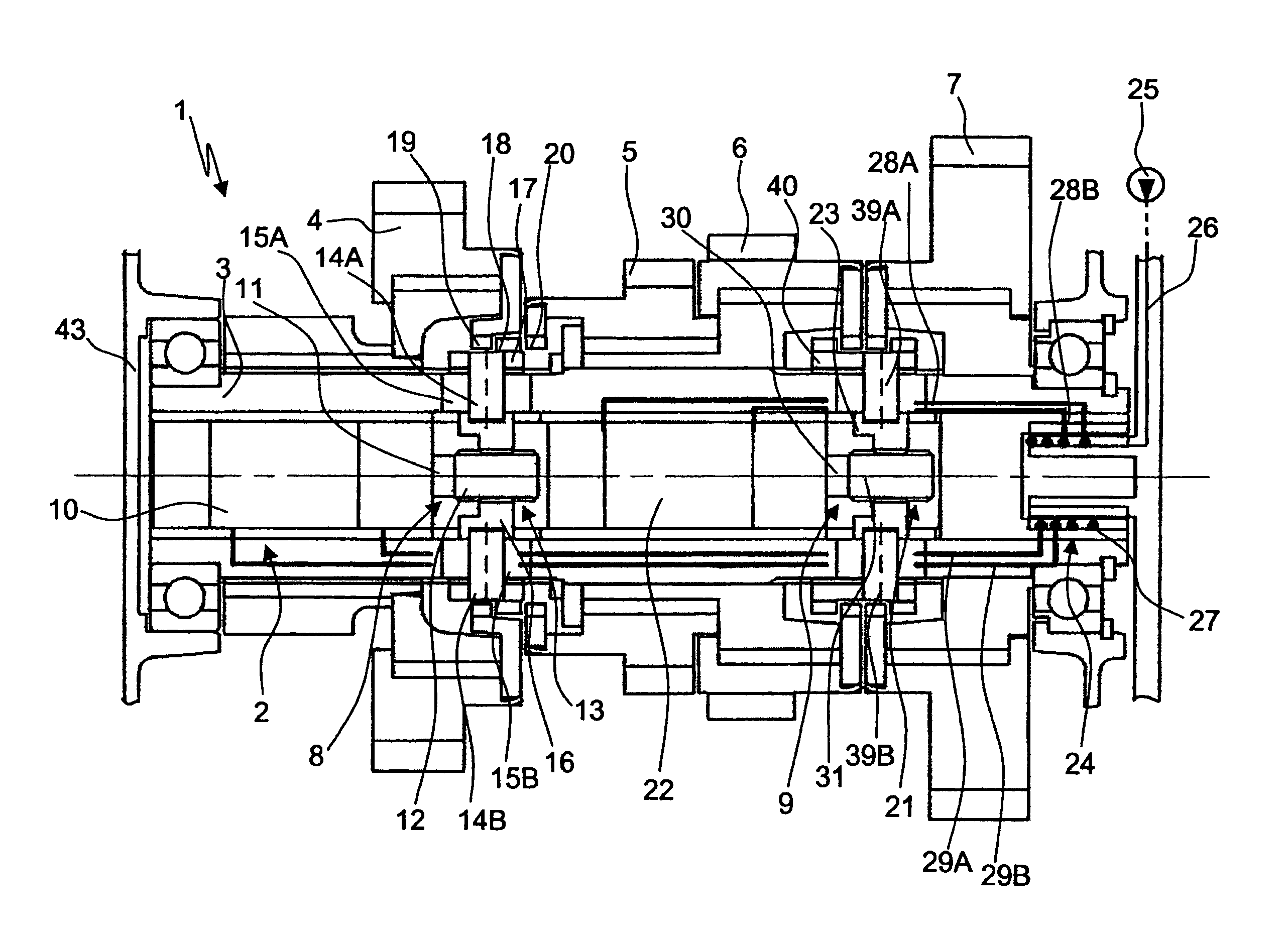
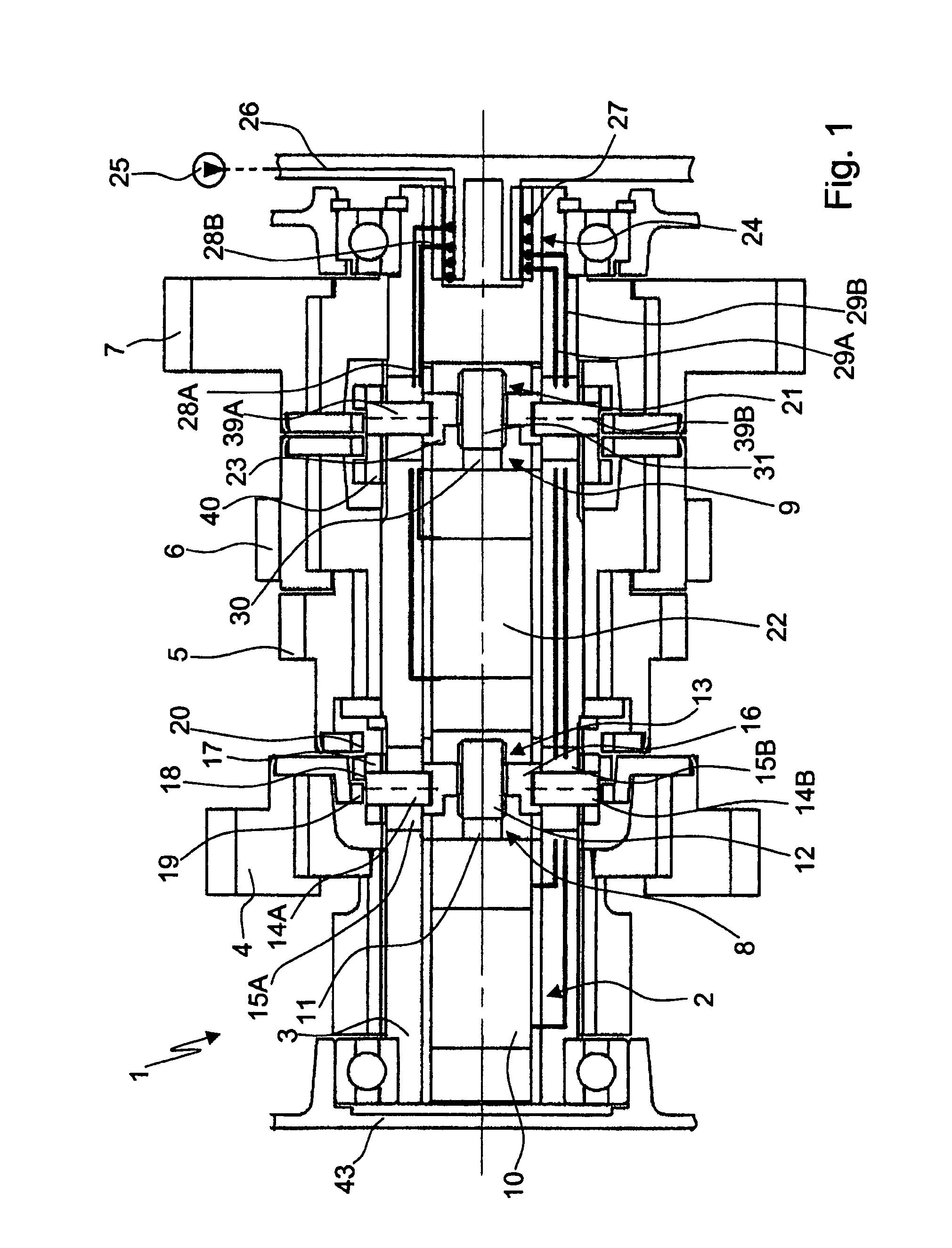
[0031]FIG. 1 shows a partial longitudinally sectioned view of a transmission device 1 made as a step-down transmission, which comprises a device 2 for rotationally fixing a shaft 3, in the form of a countershaft, with a plurality of gearwheels 4, 5, 6 and 7 made as loose wheels and mounted to rotate on the shaft 3.

[0032]The device 2 can also be used in different transmission devices, such as automated shift transmissions, double clutch transmissions or planetary transmissions, for the automated actuation of a transmission device during gearshift operations.

[0033]Parallel to the shaft 3 there is a main transmission shaft (not shown), on which are arranged a plurality of gearwheels made as fixed wheels in such manner that each fixed wheel meshes with one of the gearwheels 4 to 7.

[0034]The loose wheels 4 and 5 and the loose wheels 6 and 7 can be actuated alternately by means of engaging mechanisms 8 and 9 of the device 2 in such manner that the loose wheels 4 and 5 or 6 and 7 respectiv...


PUM


Abstract

A device for actuating a gearwheel of a transmission device. The gearwheel rotates on a shaft and can be shifted by way an engagement mechanism that includes at least one actuator that is arranged at least partially inside the shaft. The actuator can be actuated by a pressure medium to fix the gearwheel to the shaft. The actuation force required for engaging or disengaging the gearwheel can come from within the shaft. The actuator is a piston-cylinder unit which is either rotationally fixed to the shaft or rotationally fixed relative the shaft. When the actuator is rotationally fixed relative to the shaft, the active connection between the actuator and the gearwheel, which is to be shifted, includes a drive decoupling unit between the actuator and the shaft.

Description

[0001]This application is a National stage completion of PCT / EP2007 / 060818 filed Oct. 11, 2007, which claims priority from German patent application serial no. 10 2006 049 281.1 filed Oct. 19, 2006.FIELD OF THE INVENTION[0002]The invention concerns a device for actuating a gearwheel designed as a loose wheel of a transmission device.BACKGROUND OF THE INVENTION[0003]Step-down transmissions known from practice, such as dual clutch transmissions, automated manual transmission, manual transmissions or suchlike, are usually made with gearwheels mounted to rotate on a shaft, which engage with other gearwheels connected in a rotationally fixed manner on another shaft, thereby forming so-termed paired gearwheels. By alternate rotationally fixed connection of the gearwheels mounted to rotate on the shaft, the gearwheel pairs can be engaged in the force flow of a step-down transmission by means of appropriate shift elements such as synchronizers, claws, clutches or frictional elements, to pro...

Claims


Application Information

Patent Timeline
Patent Type & Authority Patents(United States)
IPC IPC(8): F16H3/14F16H3/08
CPCF16H61/30F16H63/3023Y10T74/20024Y10T74/19465Y10T74/19372F16H2063/303
Inventor MOHR, MARKREISCH, MATTHIAS
Owner ZF FRIEDRICHSHAFEN AG
Why Eureka
Try Eureka