Damaged bolt and screw removing devices

a technology of bolt and screw, which is applied in the direction of manufacturing tools, wrenches, wood boring tools, etc., can solve the problems of reducing the rotational torque required of the device, reducing the rotational torque required,

Active Publication Date: 2012-07-10
COMBINED PRODS
View PDF48 Cites 23 Cited by
  • Summary
  • Abstract
  • Description
  • Claims
  • Application Information

AI Technical Summary

Benefits of technology

[0012]It is a further object of the present invention to provide a broken bolt / screw remover bit that requires only low levels of torque to extract a fastener. A feature of the invention is that the bit has a pair of generally radially projecting cutting edges, with each of the cutting edges defining an angle with respect to the axis of the remover and a periphery of a frusto-conical surface. The cutting edges may be linear or curved. Each of these surfaces forms an acute angle with respect to the axis of the bit. An advantage of the invention is that the different cutting edge angles enhance the bite of the bit into interior surfaces of the fastener. The cutting edges can contain serrations running substantially perpendicular to the longitudinal axis of the cutting edge to provide additional purchase of the fastener. Also the serrations may form an acute or an obtuse angle with the cutting edge. The serrations allow the bit to effectively extract wayward fasteners at bit rotation speeds of as low as 0.25 RPM to as high as typical RPM values of commercially available electric screw drivers and power tools. Hand-actuated screw drivers, by comparison, are typically turned one quarter turn per wrist roll such that 30 RPM is typical for a non-powered hand tool.
[0013]Yet another object of the present invention is to provide a broken bolt / screw remover which also has drilling function. A feature of the invention is that it comprises a left-handed countersink drill bit containing serrations which extend from a cutting edge of the bit. An advantage of the invention is that the drilling feature of the remover causes more interior surfaces of the fastener to be made available to the cutting edges and the serrations, so as to assure simultaneous withdrawal of the remover with the fastener attached to the bit while leaving the threaded cavity in the workpiece intact.
[0014]Still another object of the present invention is to provide a step drill with fastener remover capabilities. A feature of an embodiment of the invention is a plurality of generally longitudinally-extending serrations interposed between axially spaced steps in the drill bit. These serrations extend in a left hand cutting fashion from a cutting edge of the bit. An advantage of the invention is that this embodiment can be utilized to extract fasteners having a myriad of different shank diameters.
[0015]Briefly, the invention provides a bit for removing a broken fastener having a direction of engagement, said bit comprising an elongated shaft with a longitudinal axis, said shaft having a first end, and a second end, said first end terminating in a drilling tip; a plurality of linear or nonlinear cutting edges extending radially from said tip, with each of the cutting edges defining a frusto-conical surface with serrations thereon, said cutting edges configured to cut into the fastener when the bit is rotated in a direction opposite to the fastener's direction of engagement; and said second end of the shaft configured to be received by a tool which provides rotational torque.

Problems solved by technology

However, the more a fastener is used, the more likely that its head becomes rounded off, or the fastener is broken, or otherwise rendered useless.
However, such devices still require considerable power to impart the rotational torque necessary to “bite” into the fastener to begin left-handed extraction.
The problem with this tool is that a recess must be present in the fastener to better facilitate removal from the workpiece.
The German tool cannot be used to remove a fastener having a slotted surface configuration unless the fastener includes a recess with a depth sufficient to allow the two cutting edges to insert therein.
Otherwise, the slotted head fastener would be damaged during removal.

Method used


Image

  • Damaged bolt and screw removing devices
  • Damaged bolt and screw removing devices
  • Damaged bolt and screw removing devices

Examples


Embodiment Construction

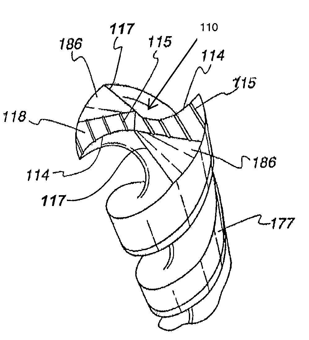
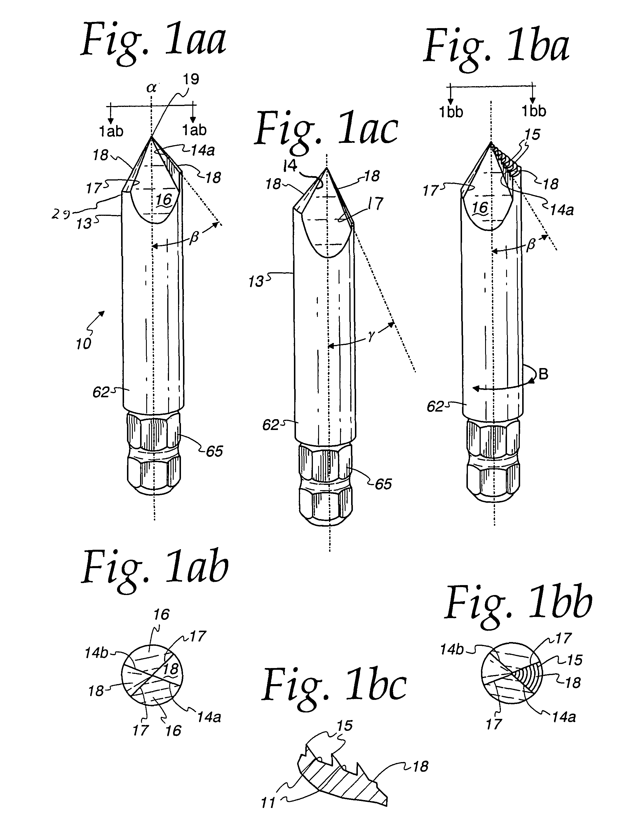
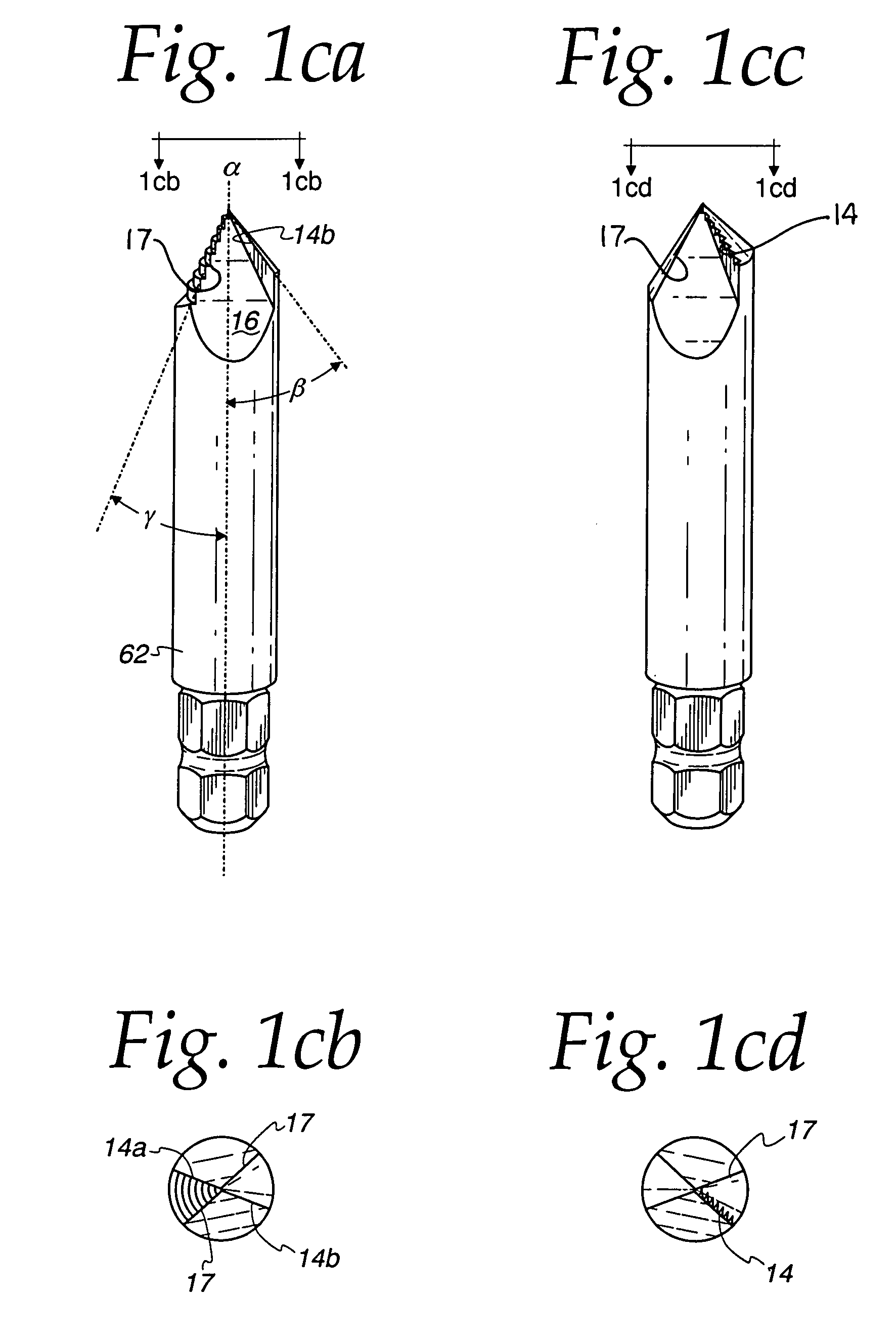
[0055]The present invention provides a bit configuration and various bit / threaded configurations on a single device to allow for easier fastener extraction. More specifically, the present invention provides a bit for removing a broken fastener having a direction of engagement, said bit comprising: (a) an elongated shaft with a longitudinal axis, said shaft having a first end, and a second end, said first end terminating in a tip region; (b) a plurality of non-cutting edges and of nonlinear cutting edges extending from said tip region, said cutting edges configured to cut into the fastener when the bit is rotated in a direction opposite to the fastener's direction of engagement, and said cutting edges and said non-cutting edges alternating with each-other; (c) a plurality of frusto-conical traction surfaces each extending from one said cutting edge to a non-cutting edge, wherein one or more of said surfaces comprise a plurality of serrations; and (d) said second end of the shaft conf...


PUM

PropertyMeasurementUnit
angleaaaaaaaaaa
angleaaaaaaaaaa
rotational torqueaaaaaaaaaa

Abstract

A bit for removing a broken fastener comprises a tip from which extend two or more notches separated by traction or biting surfaces formed from two-sided frusto-conically-shaped regions. The surfaces are bounded on one side by a nonlinear cutting edge and on the other side by a non-cutting edge and are configured to cut into the fastener when the bit is rotated in a direction opposite to the fastener's direction of engagement. Specific embodiments include configurations where the cutting edges extend at different angles with respect to the bit axis, where the biting surfaces comprise a plurality of serrations, and where the cutting edges are separated by flutes which spiral along a longitudinally extending periphery of the bit.

Description

[0001]This patent application is a Continuation in Part of U.S. Utility patent application Ser. No. 11 / 255,424 filed Oct. 22, 2005, now abandoned, which is a Continuation in Part of U.S. Utility patent application Ser. No. 10 / 831,391 filed Apr. 23, 2004, issued on Dec. 27, 2005 as U.S. Pat. No. 6,978,679 which claims the benefit of U.S. Provisional Patent Application Ser. No. 60 / 465,506; filed on Apr. 25, 2003, the entirety of these applications being incorporated herein by reference.BACKGROUND OF THE INVENTION[0002]1. Field of the Invention[0003]The present invention relates to the field of hardware tool bits, and more particularly, the present invention relates to a device for removing damaged fasteners still embedded or otherwise engaged with a workpiece.[0004]2. Description of the Prior Art[0005]The use of fasteners, such as screws, bolts, and other threaded joining devices continues to increase. However, the more a fastener is used, the more likely that its head becomes rounded...

Claims


Application Information

Patent Timeline
Patent Type & Authority Patents(United States)
IPC IPC(8): B25B13/50
CPCB23B51/009B23B51/00B23B51/02B25B27/18B23B2251/04B23B2251/48B23B2251/082B23B51/10B23B51/0081B23B51/0009B23B2251/087B23B2251/14B23B51/00035Y10T408/9095Y10T408/9097Y10T408/909
Inventor KOZAK, BURTONKOZAK, IRA
Owner COMBINED PRODS
Why Eureka
Try Eureka