
Method for controlling a vehicle drive train comprising two cooling circuits

a technology of cooling circuit and motor vehicle, which is applied in the direction of machine/engine, process and machine control, electric devices, etc., can solve the problems of increasing the electrical power consumption of the vehicle, the required life of the electric pump, and its cost, so as to improve the cooling of the engine in engine mode, improve the heating of the cabin, and improve the effect of the engine temperature ris

Inactive Publication Date: 2012-07-10
RENAULT SA
View PDF28 Cites 25 Cited by
  • Summary
  • Abstract
  • Description
  • Claims
  • Application Information

AI Technical Summary

Benefits of technology

The invention provides a method for controlling a power train of a vehicle that improves cooling of the engine and increases the temperature of the combustion engine and cabin heating. This is achieved by placing two cooling circuits that operate in the normal way, one associated with a combustion engine and the other with at least one electric member, in communication through at least one valve. The method can be used during normal operation or when the vehicle is being propelled by the electric motor alone, simultaneously with the combustion engine, or when the combustion engine is running hot. The invention also provides a vehicle comprising control means and two cooling circuits with a valve for placing them in communication with each other. The number of valves is less than or equal to two, and at least one of the valves is a three-position valve.

Problems solved by technology

However, the temperature level required for the liquid used to cool the electrotechnical components (the electrical machine or machines and the power electronic components) and the temperature level required for the liquid used to cool the combustion engine are not the same.
The use of two cooling circuits that are entirely separate or are in contact via a degassing vessel means that an additional electric water pump has to be run constantly thus increasing the electrical power consumption of the vehicle, the required life of the electric pump, and its cost.

Method used


Image

  • Method for controlling a vehicle drive train comprising two cooling circuits
  • Method for controlling a vehicle drive train comprising two cooling circuits
  • Method for controlling a vehicle drive train comprising two cooling circuits

Examples


Embodiment Construction

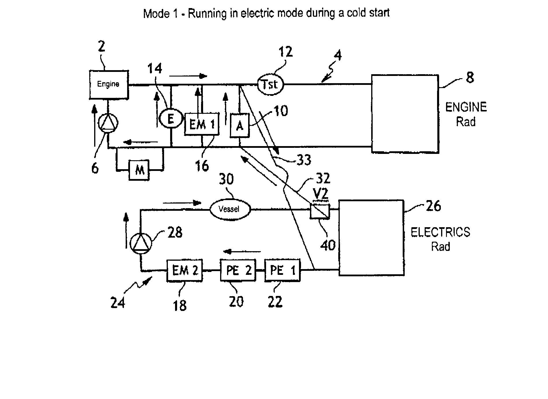
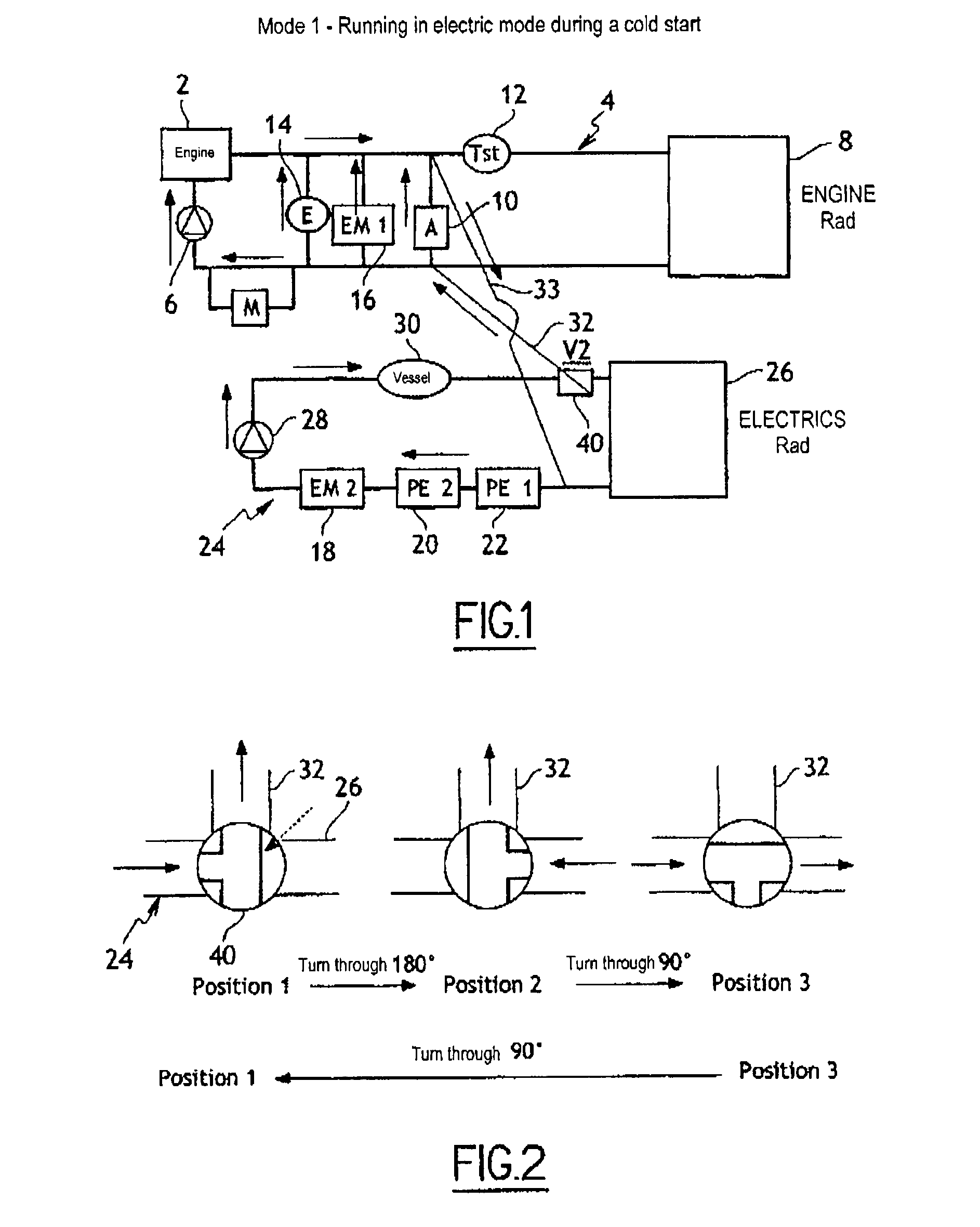
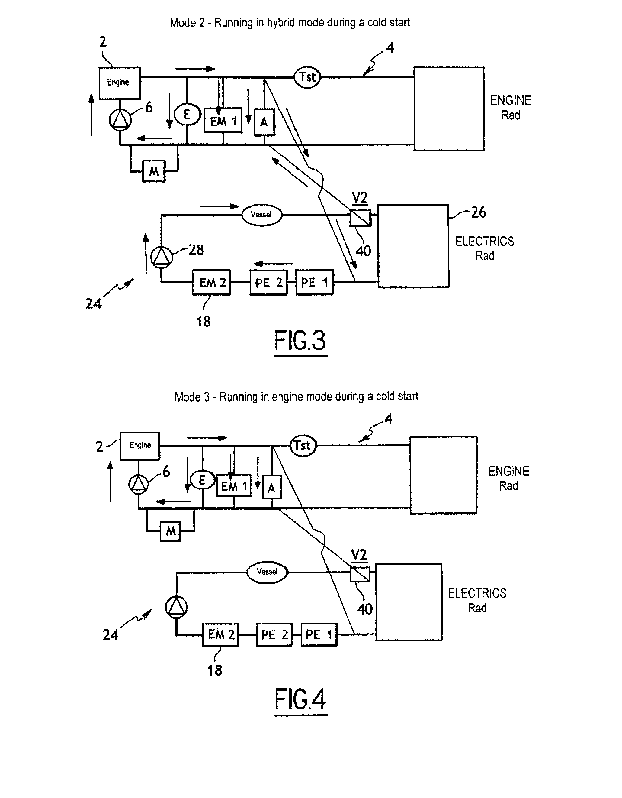
[0033]A preferred embodiment of a vehicle according to the invention is illustrated in FIG. 1. This figure shows that the vehicle comprises a combustion engine 2 associated with a cooling circuit 4. This circuit comprises a water pump 6 which is either mechanical and driven off the combustion engine, or electric. The circuit 4 contains a cooling radiator 8 known as the high-temperature radiator or engine radiator. The circuit 4 also comprises a unit heater 10 or cabin heating radiator. This same circuit in this instance comprises a thermostat 12 in the form of a wax thermostat, a controlled thermostat or alternatively a controlled valve allowing the temperature of the liquid coolant flowing through the circuit 4 to be regulated. The circuit may comprise other conventional components according to the technical design of the engine and according to whether it is a controlled-ignition or compression-ignition engine. These components might, for example, be:[0034]a liquid coolant / engine ...


PUM


Abstract

A method for controlling a vehicle drive train, which communicates or maintains in communication via at least one valve two cooling circuits operating normally and respectively associated with a heat engine and with at least one electrical member.

Description

BACKGROUND[0001]The invention relates to the control of motor vehicle power trains and in particular to the control of their cooling circuits.[0002]It is known that hybrid vehicles are equipped with a power train comprising a combustion engine, one or two electrical machines, power electronic components and a power battery.[0003]The combustion engine can be used to recharge the batteries via a generator and / or to provide the vehicle with traction or propulsion. When the combustion engine simply recharges the vehicle batteries, it is said to be a series hybrid vehicle. When the combustion engine provides the vehicle with traction and / or propulsion, it is then said to be a parallel hybrid vehicle.[0004]Whatever the architecture connecting the combustion engine and the electrical machine or machines, it is necessary to cool the combustion engine, the electrical machine or machines, and the power electronic components.[0005]However, the temperature level required for the liquid used to ...

Claims


Application Information

Patent Timeline
Patent Type & Authority Patents(United States)
IPC IPC(8): B60W10/30B60K6/26B60L50/16
CPCB60K6/26B60K11/02F01P7/165B60K2001/003F01P2005/105F01P2031/30B60K2001/006F01P2060/02F01P2060/04F01P2060/045F01P2060/08F01P2060/16F01P2050/24B60L1/003B60L1/02B60L3/0023B60L3/003B60L3/0061B60L2240/34B60L2240/425B60L2240/445B60L2240/525B60L2260/22B60L50/15B60L50/16Y02T10/64Y02T10/7072Y02T90/16
Inventor ROUAUD, CEDRICYU, ROBERT
Owner RENAULT SA
Learn More