Low noise cooling device

a cooling device and low noise technology, applied in the direction of machines/engines, positive displacement liquid engines, light and heating apparatus, etc., can solve the problems of reducing requiring subsonic frequencies or mechanical symmetry to achieve satisfactory noise reduction, and weakening each other's sound waves, etc., to reduce the sound level, reduce the range of applications, and reduce the effect of cos

Active Publication Date: 2012-07-10
SIGNIFY HLDG BV
View PDF15 Cites 2 Cited by
  • Summary
  • Abstract
  • Description
  • Claims
  • Application Information

AI Technical Summary

Benefits of technology

[0006]In view of the above, an object of the invention is to solve or at least reduce the problems discussed above. In particular, an object is to extend the range of applications for these cooling devices by providing a way to reduce the sound level in a pulsating cooling system also for systems where mechanical symmetry is not practical while maintaining a low cost.
[0007]According to an aspect of the invention, there is provided a cooling device using pulsating fluid for cooling of an object, comprising a transducer having a membrane adapted to generate pressure waves at a working frequency (fw), and a cavity enclosing a first side of the membrane, the cavity having at least one opening adapted to emit a pulsating net output fluid flow towards the object, wherein the opening is in communication with a second side of the membrane. The cavity is sufficiently small to prevent fluid in the cavity from acting as a spring in a resonating mass-spring system in the working range. This is advantageous as a volume velocity (u1) of the membrane is essentially equal to a volume velocity at the opening. Furthermore, a volume velocity (u1) at the opening is essentially equal to a volume velocity (u1′) at the second side of the membrane, apart from a minus sign. Thus, at the working frequency the pulsating net output fluid can be largely cancelled due to the counter phase with the pressure waves on the second side of the membrane resulting in a close to zero far-field volume velocity. Thus a low sound level is achieved, at a low cost, without requiring mechanical symmetry.
[0010]The invention is based on the idea that by having the volume of the cavity sufficiently small, the fluid therein can be considered as essentially incompressible and is prevented from acting as a spring in a resonating mass-spring system. An example of such a resonating system, which is prevented by the invention, is a Helmholtz resonator. As the fluid is essentially incompressible the volume velocity at the opening and the rear of the transducer will be essentially equal (apart from the sign). Thereby, at the working frequency the pulsating net output fluid can be largely cancelled due to the counter phase with the pressure waves on the second side of the membrane resulting in a close to zero far-field volume velocity. Thus a lower sound level is achieved, at a low cost, without requiring mechanical symmetry.
[0011]The opening can be connected to the cavity via a channel, allowing more design freedom, as the channel can be formed to direct the fluid stream towards a desired location and in a desired direction. To prevent the channel from acting as a transmission line, the channel preferably has a length (Lp) which is less than λ / 20, where λ is the wave length in the fluid corresponding to f=fw.

Problems solved by technology

Since the sound waves that are generated at the nozzles have opposite phases, the sound waves weaken each other.
However, a drawback with previously proposed systems, e.g. as disclosed in US 2006 / 0237171, is that they require subsonic frequencies or mechanical symmetry to achieve satisfactory noise reduction.
This limits the range of applications as there often are inherent mechanical.

Method used


Image

  • Low noise cooling device
  • Low noise cooling device
  • Low noise cooling device

Examples


Embodiment Construction

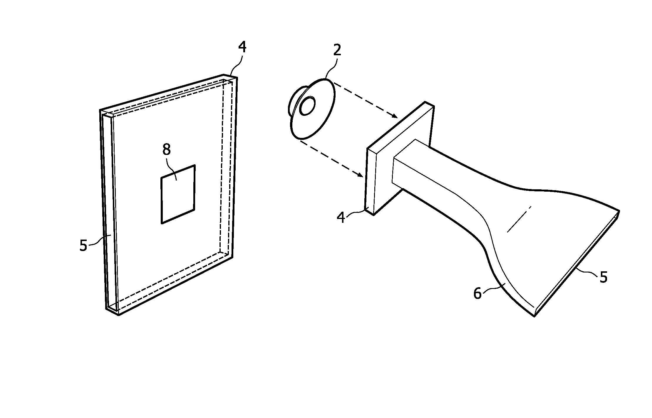
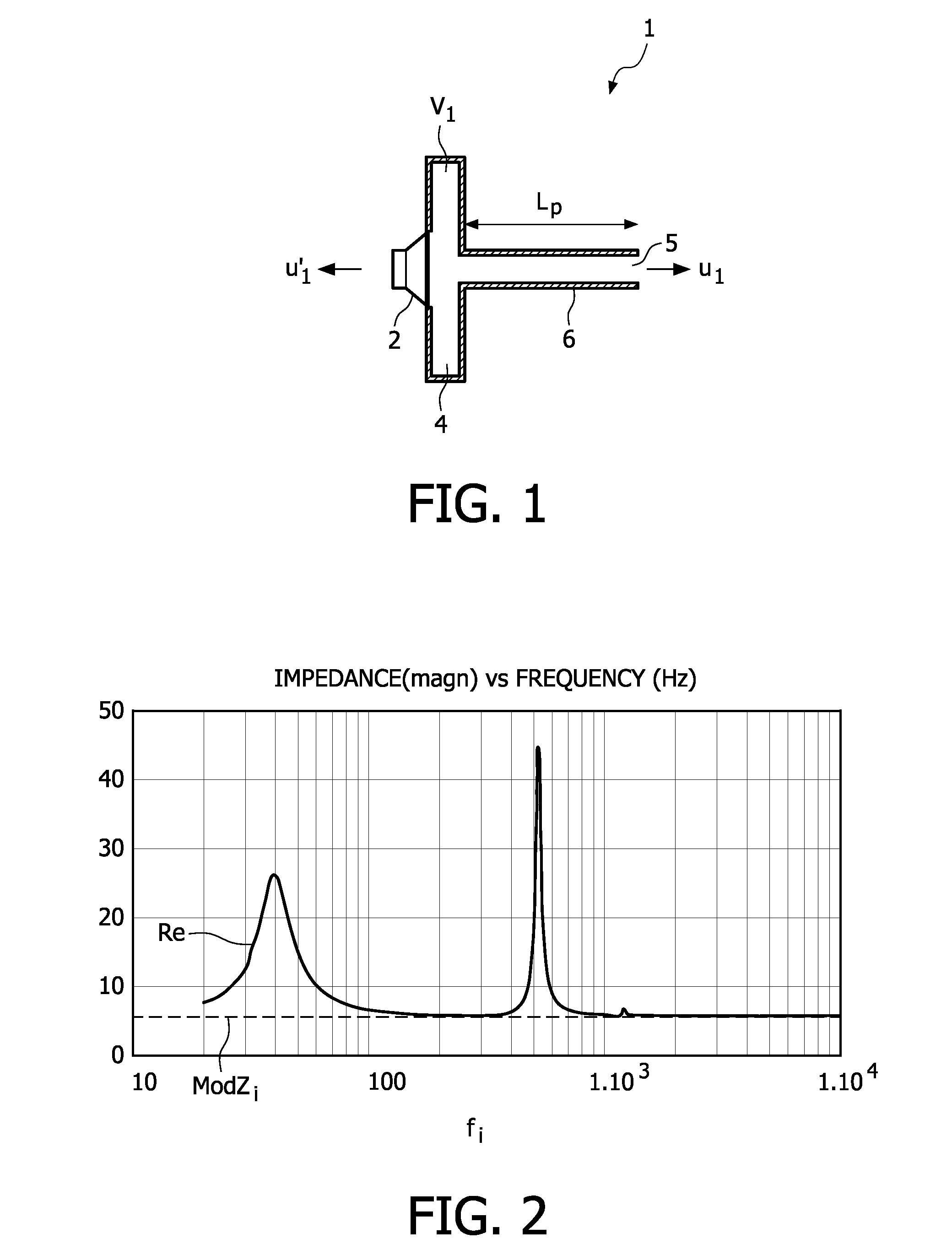
[0031]The cooling device 1 in FIG. 1 comprises a transducer 2 having a membrane adapted to generate pressure waves at a working frequency (fw). The transducer 2 is here illustrated as a loudspeaker, but is not limited thereto. On the contrary any transducer capable of generating a pressure wave could be used. A cavity 4 is arranged in front of the transducer 2, thereby enclosing a first side of the transducer membrane. The fluid in the cavity 4 is here air. The cavity 4 is in communication with the environment outside the cavity through an opening 5. Furthermore, the opening is in communication with the rear of the transducer (i.e. the side of the membrane facing away from the cavity). The opening 5 is connected to the cavity 4 via a channel 6, having a uniform shape and size throughout its extension, here in the form of a cylindrical tube 6. However, the channel may be in a variety of shapes. For example, the channel may have a rectangular cross-section. Also, the cross-section may...


PUM


Abstract

A cooling device (1) using pulsating fluid for cooling of an object, comprising: a transducer (2) having a membrane adapted to generate pressure waves at a working frequency (fw), and a cavity (4) enclosing a first side of the membrane. The cavity (4) has at least one opening (5) adapted to emit a pulsating net output fluid flow towards the object, wherein the opening (5) is in communication with a second side of the membrane. The cavity (4) is sufficiently small to prevent fluid in the cavity (4) from acting as a spring in a resonating mass-spring system in the working range. This is advantageous as a volume velocity (u1) at the opening is essentially equal to a volume velocity (u1′) at the second side of the membrane, apart from a minus sign. Thus, at the working frequency the pulsating net output fluid can be largely cancelled due to the counter phase with the pressure waves on the second side of the membrane resulting in a close to zero far-field volume velocity. Thus a low sound level is achieved, at a low cost, without requiring mechanical symmetry.

Description

TECHNICAL FIELD[0001]The present invention relates to a cooling device using pulsating fluid for cooling of an object, comprising: a transducer having a membrane adapted to generate pressure waves at a working frequency (fw), and a cavity enclosing a first side of the membrane, the cavity having at least one opening adapted to emit a pulsating net output fluid flow towards the object, wherein the opening is in communication with a second side of the membrane.[0002]The present invention further relates to an electronic device and an illumination device comprising such a cooling device.BACKGROUND OF THE INVENTION[0003]The need for cooling has increased in various applications due to higher heat flux densities resulting from newly developed electronic devices, being, for example, more compact and / or higher power than traditional devices. Examples of such improved devices include, for example, higher power semiconductor light-sources, such as lasers or light-emitting diodes, RF power de...

Claims


Application Information

Patent Timeline
Patent Type & Authority Patents(United States)
IPC IPC(8): H05K7/20
CPCF04F7/00F04D33/00F04D23/006F04D35/00H05K7/20
Inventor AARTS, RONALDUS MARIALASANCE, CLEMENS JOHANNES MARIANIEUWENDIJK, JORIS ADELBERT MARIAOUWELTJES, OKKE
Owner SIGNIFY HLDG BV
Why Eureka
Try Eureka