
Light guide strip structure

a technology of light guide and sleeve, which is applied in the direction of instruments, color-music instruments, applications, etc., can solve the problems of deteriorating brightness, interference of light ray reflected from one surface, and deterioration of the brightness of the light guide structure, in which the core body is coated with the sleeve, so as to improve the problem of interference between light rays and the cost

Inactive Publication Date: 2012-07-10
HO CHANG HSIEN
View PDF7 Cites 11 Cited by
  • Summary
  • Abstract
  • Description
  • Claims
  • Application Information

AI Technical Summary

Benefits of technology

"The present invention provides a light guide strip structure with neon effect that is simplified and manufactured at lower cost. The structure minimizes bright-and-dark stripes and diffraction while improving interference between light rays. The main body has a transparent main body with a light-scattering surface and a color band with a reflective index greater than that of the main body. The light is refracted and reflected between the main body and the color band and scattered from the surface of the main body to enhance brightness and overcome the problem of vagueness existing in the prior art. The ratio of the cross-sectional area of the main body to the cross-sectional area of the color band ranges from about 20:1 to 90:1. Multiple segments of color bands are arranged in the main body at intervals along the axis of the main body. The main body is composed of two halves with a color band on at least one of the two halves."

Problems solved by technology

However, the sleeve will blur the scattered light and deteriorate the brightness.
It is very possible that the light ray reflected from one of the surfaces is interfered with and offset by the light ray reflected from the other of the surfaces.
In other words, due to interference, the brightness of such light guide structure, in which the core body is coated with the sleeve, will be deteriorated.
However, this makes it more complicated to manufacture the light guide structure.
However, the protective layer or the sleeve also will blur the scattered light and deteriorate the brightness and visual effect.
As known by those skilled in this field, it is relatively complicated to manufacture such light guide structure with the light-scattering particles or diffuser particles.
That is, the light ray reflected from the inner surface of the sleeve and the outer surface of the core body, which is very close to the inner surface of the sleeve, will interfere with each other to produce interference stripes and reduce the brightness of the light rays.

Method used


Image

  • Light guide strip structure
  • Light guide strip structure
  • Light guide strip structure

Examples


Embodiment Construction

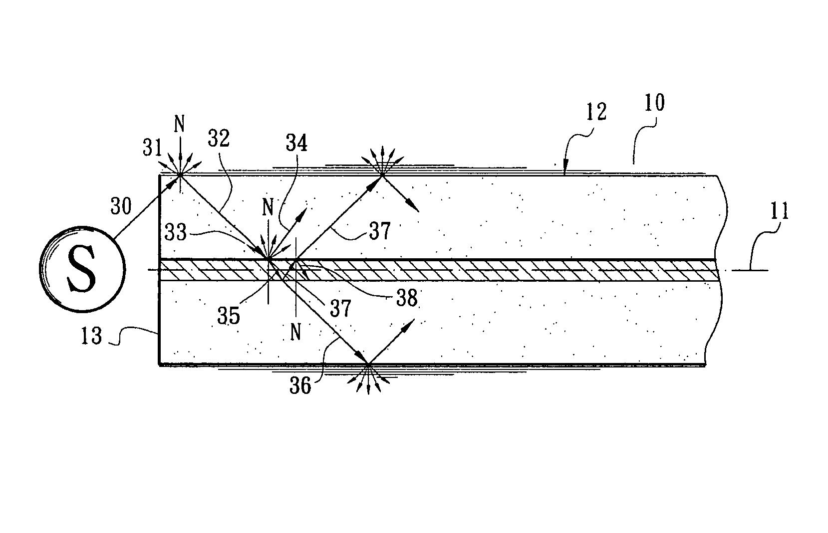
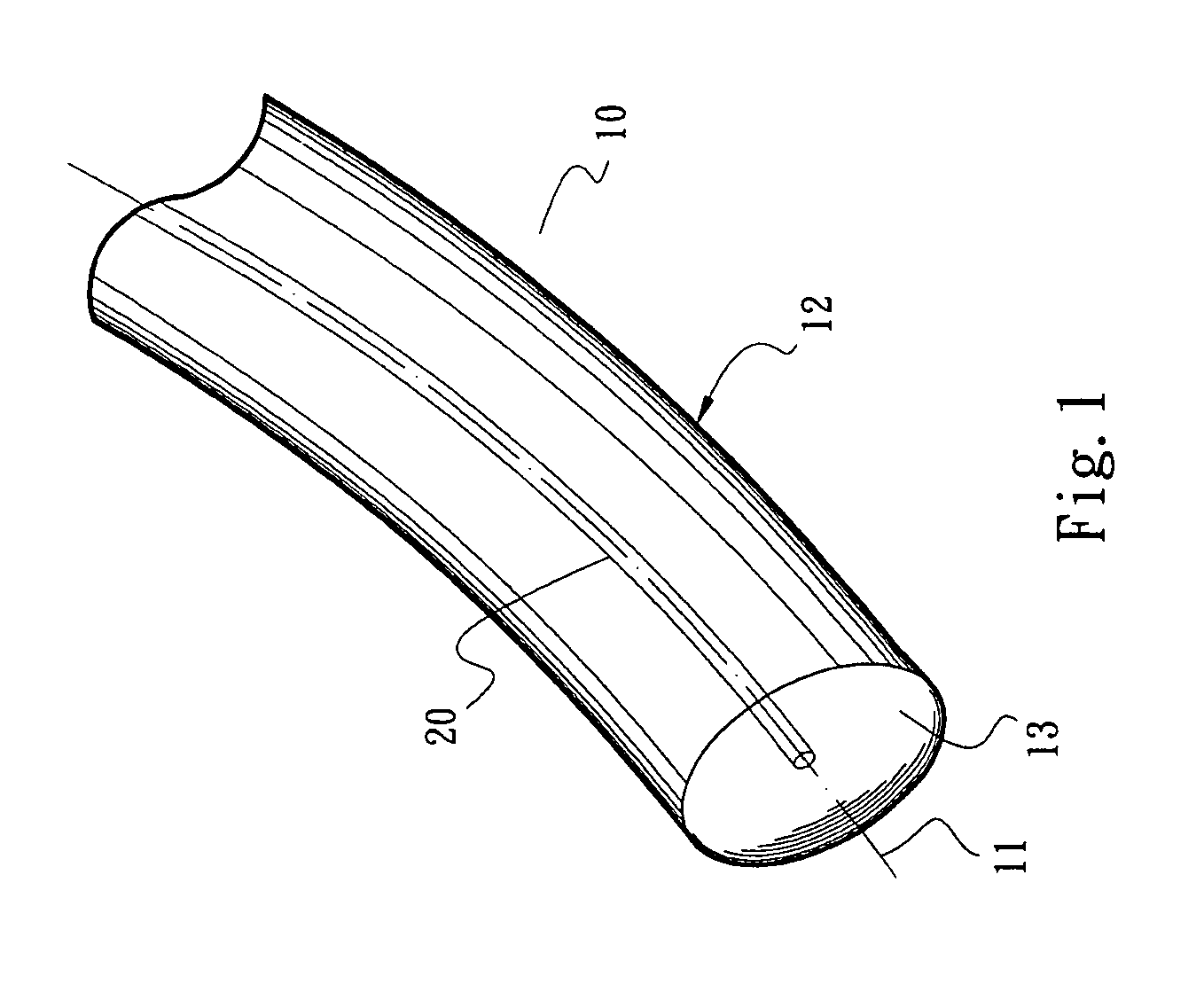
[0032]Please refer to FIGS. 1 and 2. The light guide strip structure with neon effect of the present invention includes a main body 10 and at least one color band 20. The main body 10 is made of transparent plastic, PMMA, PU, glass, resin, thermoplastic plastic material or the like. (The materials of the main body have been disclosed in the prior art and thus will not be further described hereinafter.) According to a preferred embodiment, the main body 10 is a transparent flexible body with good refractivity and transparency (or transmission performance). In this embodiment, the main body 10 is formed with a circular cross-section and has a central axis 11 and a light-scattering surface 12. Alternatively, the main body 10 can be formed with any other suitable geometric shape.

[0033]In this embodiment, the color band 20 is a colored band body or strip body. The color band 20 is embedded in the main body 10 substantially at the axis 11 thereof. The color band 20 can be coated with silv...


PUM


Abstract

A light guide strip structure with neon effect, which is manufactured at lower cost and can be used with the bright-and-dark stripes or diffraction and interference between the light rays minimized. The light guide strip structure includes a transparent main body having a light-scattering surface and a color band disposed in the main body. The color band has a reflective index greater than that of the main body, whereby most of the light is reflected back to the main body and only a minor part of the light enters the color band to create neon effect. The light entering the main body substantially travels along an axis thereof. The light is refracted and reflected between the main body and the color band and scattered from the surface of the main body to enhance brightness and overcome the problem of vagueness.

Description

BACKGROUND OF THE INVENTION[0001]The present invention relates generally to a light guide structure, and more particularly to a light guide strip structure composed of a transparent main body and a color band embedded in the main body. The light is refracted and reflected between the main body and the color band and scattered from the surface of the main body to create neon effect.[0002]A conventional light guide generally includes a transparent core body and a protective layer or a thin sleeve coated on the surface of the core body. The core body is made of a thermoplastic plastic material such as PC, PU, Ethyl, Methyl Acrylate or the like polymer material. The protective layer or sleeve is made of PE material. For example, U.S. Pat. No. 4,422,719, entitled “optical distribution system including light guide”, discloses a combination of transparent core body and a semitransparent sleeve. The sleeve has a refractive index greater than that of the core body to enhance light reflection...

Claims


Application Information

Patent Timeline
Patent Type & Authority Patents(United States)
IPC IPC(8): G02B6/00F21V8/00
CPCG02B6/001
Inventor HO, CHANG-HSIEN
Owner HO CHANG HSIEN
Learn More