
Anterior inflation balloon

a balloon and balloon technology, applied in the field of surgical procedures, can solve the problems of reducing the recovery period, reducing the likelihood of height restoration of the vertebrae, and presenting minimally invasive procedures, so as to enhance the likelihood of height restoration of the vertebrae, and the distal expansion is grea

Active Publication Date: 2012-07-17
KYPHON
View PDF16 Cites 16 Cited by
  • Summary
  • Abstract
  • Description
  • Claims
  • Application Information

AI Technical Summary

Benefits of technology

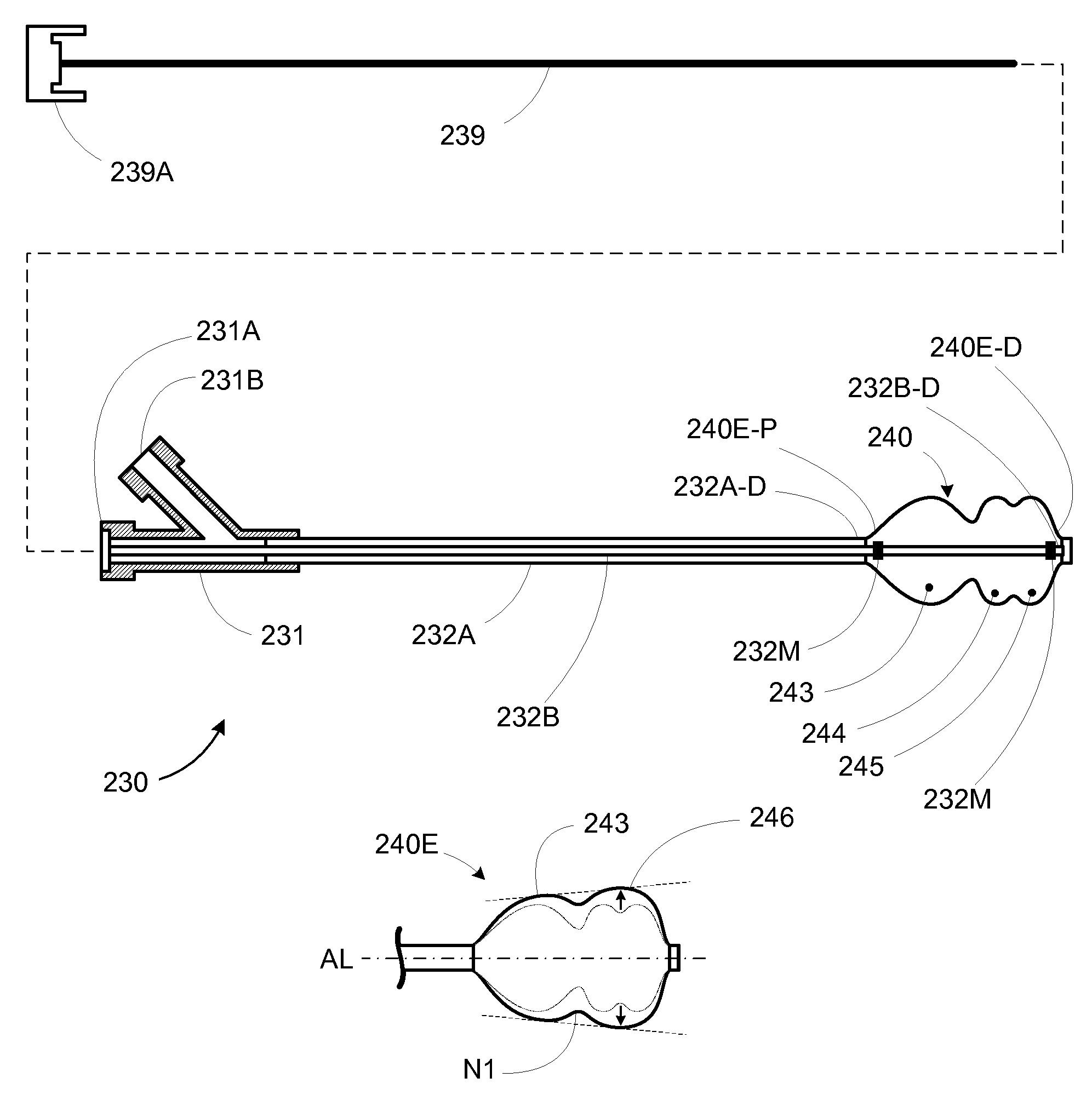
[0015]By providing a bone tamp with an inflatable structure having an expansion profile that exhibits greater distal expansion than proximal expansion (i.e., outwardly tapering), a kyphoplasty procedure can be performed in which lifting forces are more effectively applied to the endplates of a collapsed vertebral body, thereby enhancing the likelihood of height restoration of the vertebral body during the procedure.
[0020]In various other embodiments, the durability and abrasion-resistance of a multi-lobed balloon can be enhanced by forming the lobes such that the non-distended wall thickness between the lobes is greater than the non-distended wall thicknesses at the locations of the maximum non-distended radial diameters of the lobes. For example, in a tri-lobed balloon, the section of the balloon between the middle and distal lobes is where the greatest inflation will generally occur. Therefore, a thick wall in that region will result in a much more robust and resilient balloon wall upon inflation.
[0023]In a procedure such as kyphoplasty the outwardly tapering expansion profile of the inflatable bone tamp allows the inflation force of the bone tamp to be more effectively directed towards the endplates of the fractured vertebra. This in turn enhances the ability of the bone tamp to restore the height of the vertebra, rather than simply compacting a larger portion of cancellous bone within the vertebra.

Problems solved by technology

In contrast to an open procedure for the same purpose, a minimally invasive procedure will generally be less traumatic to the patient and result in a reduced recovery period.
However, there are numerous challenges that minimally invasive procedures present.
For example, minimally invasive procedures are typically more time-consuming than their open procedure analogues due to the challenges of working within a constrained operative pathway.
In addition, without direct visual feedback into the operative location, accurately selecting, sizing, placing, and / or applying minimally invasive surgical instruments and / or treatment materials / devices can be difficult.
For example, for many individuals in our aging world population, undiagnosed and / or untreatable bone strength losses have weakened these individuals' bones to a point that even normal daily activities pose a significant threat of fracture.
In one common scenario, when the bones of the spine are sufficiently weakened, the compressive forces in the spine can cause fracture and / or deformation of the vertebral bodies.
For sufficiently weakened bone, even normal daily activities like walking down steps or carrying groceries can cause a collapse of one or more spinal bones.
Fractures such as vertebral compression fractures often result in episodes of pain that are chronic and intense.
Aside from the pain caused by the fracture itself, the involvement of the spinal column can result in pinched and / or damaged nerves, causing paralysis, loss of function, and intense pain which radiates throughout the patient's body.
Even where nerves are not affected, however, the intense pain associated with all types of fractures is debilitating, resulting in a great deal of stress, impaired mobility and other long-term consequences.
For example, progressive spinal fractures can, over time, cause serious deformation of the spine (“kyphosis”), giving an individual a hunched-back appearance, and can also result in significantly reduced lung capacity and increased mortality.
Because patients with these problems are typically older, and often suffer from various other significant health complications, many of these individuals are unable to tolerate invasive surgery.
In general, a balloon exhibiting symmetrical free expansion will expand along a path of least resistance when inflated within its target environment, which can result in less than optimal procedure results.

Method used


Image

  • Anterior inflation balloon
  • Anterior inflation balloon
  • Anterior inflation balloon

Examples


Embodiment Construction

[0032]By providing a bone tamp with an inflatable structure having an expansion profile that exhibits greater distal expansion than proximal expansion (i.e., outwardly tapering), a kyphoplasty procedure can be performed in which lifting forces are more effectively applied to the endplates of a collapsed vertebral body, thereby enhancing the likelihood of height restoration of the vertebral body during the procedure.

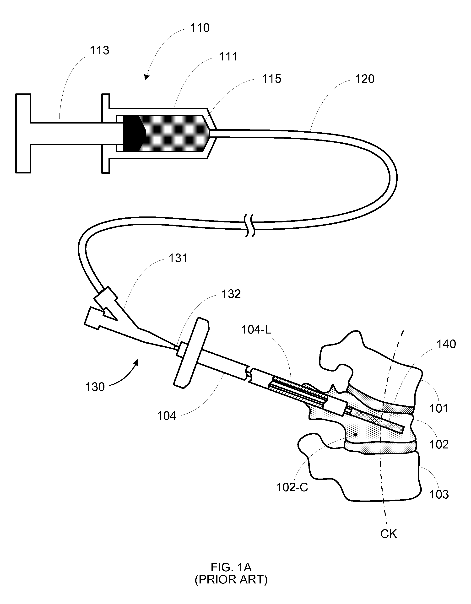
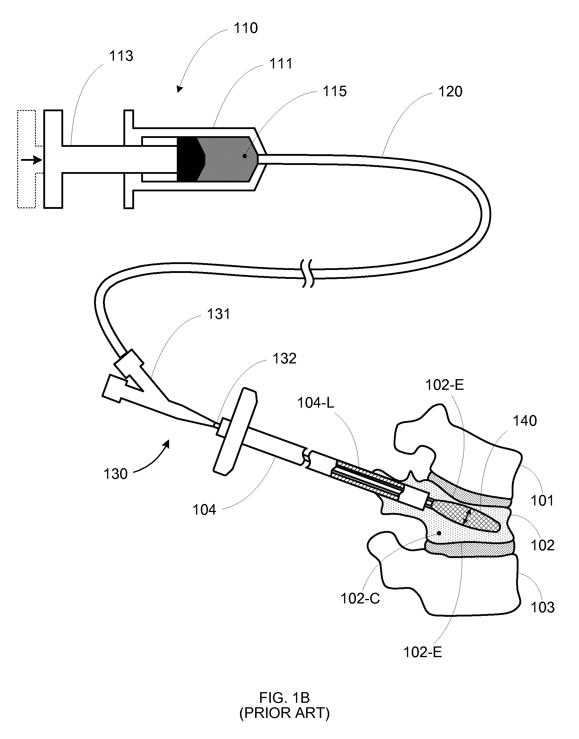
[0033]FIGS. 2A-2H show an exemplary kyphoplasty procedure using an inflatable bone tamp exhibiting an outwardly tapering inflation profile. FIG. 2A shows a portion of a human vertebral column having vertebrae 201, 202, and 203. Vertebra 202 has collapsed due to a vertebral compression fracture (VCF) 202-F that could be the result of osteoporosis, cancer-related weakening of the bone, and / or physical trauma. The abnormal curvature CK of the spine caused by VCF 202-F can lead to severe pain and further fracturing of adjacent vertebral bodies.

[0034]FIG. 2B shows a cannula 20...


PUM


Abstract

An inflatable bone tamp for performing a minimally invasive surgical procedure includes an inflatable structure having at least three contiguous lobes, that when inflated, cause the inflatable structure to exhibits an outwardly tapering expansion profile. By forming the inflatable structure such that the reduced-diameter junction(s) between the lobes has a greater wall thickness then the adjacent lobes, the durability and abrasion-resistance of the inflatable bone tamp can be increased.

Description

CROSS-REFERENCE TO RELATED APPLICATIONS[0001]This application is a continuation-in-part of application Ser. No. 12 / 608,935, filed Oct. 29, 2009.FIELD OF THE INVENTION[0002]The invention relates to a system and method for performing a surgical procedure, and in particular, to an inflatable device that exhibits greater distal than proximal expansion to manipulate bone.BACKGROUND OF THE INVENTION[0003]A minimally invasive procedure is a medical procedure that is performed through the skin or an anatomical opening. In contrast to an open procedure for the same purpose, a minimally invasive procedure will generally be less traumatic to the patient and result in a reduced recovery period.[0004]However, there are numerous challenges that minimally invasive procedures present. For example, minimally invasive procedures are typically more time-consuming than their open procedure analogues due to the challenges of working within a constrained operative pathway. In addition, without direct vis...

Claims


Application Information

Patent Timeline
Patent Type & Authority Patents(United States)
IPC IPC(8): A61M29/00
CPCA61B17/8822A61B17/8855A61M25/1018A61B19/54A61B2017/00557A61M25/10185A61B90/39
Inventor AUYOUNG, BRYAN J.CHAN, HESTERSAPIDA, WARREN C.JENKINS, TODD W.
Owner KYPHON
Learn More