Photographic control system, devices and method

a control system and photographic technology, applied in the field of peripheral devices, can solve the problems of increasing the risk of implementing an inferior radio solution into the lighting device of many lighting component manufactures, affecting the quality of lighting components, etc., and achieves the effects of low cost, easy transportation, and wide acceptan

Inactive Publication Date: 2012-07-17
PROMARK INT
View PDF2 Cites 17 Cited by
  • Summary
  • Abstract
  • Description
  • Claims
  • Application Information

AI Technical Summary

Benefits of technology

[0007]Photographic peripheral device manufacturers adopting a substantially standardized radio communications system could enjoy “turn-key” type solutions, requiring very low research and development cost, and short time to market. And since end user training time is minimized, a manufacturer's customers would more likely purchase new, and improved, RF enabled products.
[0032]Embodiments according to the current disclosure thus may provide for several key needs sought by the industry's end users, as well as the industry's equipment manufacturers. Firstly, embodiments may provide a substantially standardized control system, with the potential for wide acceptance, which may be operable across many makes, models, and brands of controllable device, and that may have a low cost of implementation for manufacturers of controllable device. Secondly, the manufacturers may choose to license their own internal proprietary features on a user by user basis while at the same time providing a substantially standardized and widely accepted communication system to a diverse user base.

Problems solved by technology

Lighting equipment manufacturers attempting to design proprietary RF synchronization into their lights often find that mastering both lighting engineering and RF engineering is costly and time consuming.
Complying with FCC (Federal Communications Commission) certification requirements also adds cost and time to development cycles.
Often the risk of implementing an inferior radio solution into their lighting devices is too high for many lighting component manufactures.
Many end users, particularly novices to photography or advanced photographic lighting, find the task of learning to control lighting equipment to be a steep learning curve, which often prevents them from fully understanding the function of their lighting equipment.
There may only be one round of certification and tooling costs.
As the EM is likely to be the most expensive part of the system, an end user may purchase the EM only if they require wireless functionality of their equipment.
The serial number may be difficult to alter or tamper with by an end user.

Method used


Image

  • Photographic control system, devices and method
  • Photographic control system, devices and method
  • Photographic control system, devices and method

Examples


Embodiment Construction

[0103]While the present system, devices and method, are described with reference to several illustrative embodiments described herein, it should be clear that the present invention should not be limited to such embodiments. Therefore, the description of the embodiments provided herein is illustrative of the present invention and should not limit the scope of the invention as claimed. In addition, while the following description references drawings showing particular configurations and proportions, it will be appreciated that the invention may be configured to have other configurations and proportions.

[0104]The description may use perspective-based descriptions such as up / down, back / front, and top / bottom. Such descriptions are merely used to facilitate the discussion and are not intended to restrict the application of embodiments of the present invention.

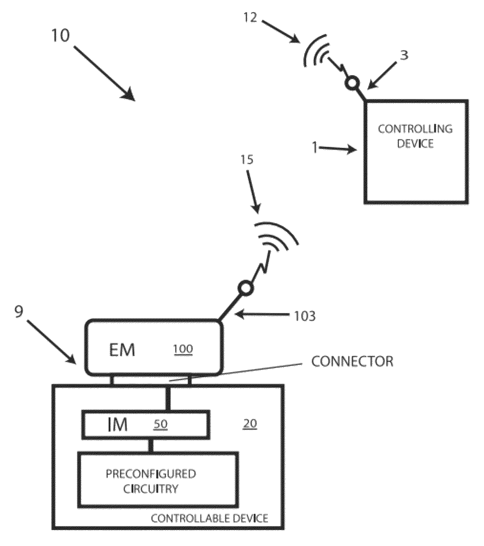
[0105]FIG. 1 is a schematic diagram generally illustrating an example system 10 for controlling a piece of controllable equipment, ...


PUM


Abstract

A control system for use with preconfigured photographic equipment that includes a controllable photographic device controlled by a controlling photographic device is disclosed. The controllable photographic device has a housing, and a device circuit having an upstream portion and a downstream portion coupled by control lines within the housing. An internal module may be located within the housing and includes a signal detecting arrangement configured to be coupled with the control lines between the upstream and downstream portions. The system may also include an external module configured to be located outside of the housing, and coupled with the internal module. The external module may include a signal receiving device capable of receiving a wireless control signal from the controlling photographic device, and to cause a module generated signal to be sent by the internal module to the downstream portion upon receipt of the wireless control signal.

Description

CROSS-REFERENCES TO RELATED APPLICATIONS[0001]This application claims the benefit of U.S. Provisional Patent Application No. 61 / 221,083 filed Jun. 28, 2009, entitled WIRELESS CAMERA FLASH RADIO DATA MODULE SET and U.S. Provisional Patent Application No. 61 / 293,145 filed Jan. 7, 2010, entitled DATABASE LICENSING AND CUSTOMER SERVICE SYSTEM FOR RADIO WIRELESS CAMERA AND FLASH SYSTEMS and incorporates the disclosures of those applications by reference.BACKGROUND[0002]This application relates generally to peripheral devices used in photography systems. More specifically, this application relates to a system, devices, and methods to augment a large number of dissimilar groups of photographic peripheral devices to enable a substantially standardized intercommunication protocol between the peripheral devices and a various cameras, and between the peripheral devices themselves.BACKGROUND AND SUMMARY[0003]For many years companies have introduced various combinations of radio frequency (“RF”)...

Claims


Application Information

Patent Timeline
Patent Type & Authority Patents(United States)
IPC IPC(8): G03B17/00
CPCG03B15/05H04N5/2256H04N5/23203G03B2215/0557H04N23/56H04N23/66
Inventor KING, KEVIN JAMESKACHEVAS, MATTHEW M
Owner PROMARK INT
Why Eureka
Try Eureka