
Damper for continuously variably adjusting damping force

a damping force and variable technology, applied in the direction of shock absorbers, wound springs, mechanical devices, etc., can solve problems such as the degradation of ride comfort, and achieve the effect of stably conducting a damping operation

Active Publication Date: 2012-07-24
S&T DAEWOO
View PDF9 Cites 5 Cited by
  • Summary
  • Abstract
  • Description
  • Claims
  • Application Information

AI Technical Summary

Benefits of technology

The present invention is a liquid crystal display device and a method of driving it that solves problems of the related art. It provides a damper that can continuously adjust the damping force and maintain a stable reference height for conducting the damping operation. The damper includes a cylinder, piston rod, piston valve, MR fluid, and volume compensation means. The volume compensation means includes a floating plunger, coil spring, and support cup. The technical effects of the invention include improved image quality, reduced power consumption, and stable operation.

Problems solved by technology

Therefore, there is growing concern about vehicle overturn accident, and rolling action while running is intensified thus there is concern about degradation of ride comfort.

Method used


Image

  • Damper for continuously variably adjusting damping force
  • Damper for continuously variably adjusting damping force
  • Damper for continuously variably adjusting damping force

Examples


Embodiment Construction

[0036]Reference will now be made in detail to the embodiments of the present invention, examples of which are illustrated in the accompanying drawings.

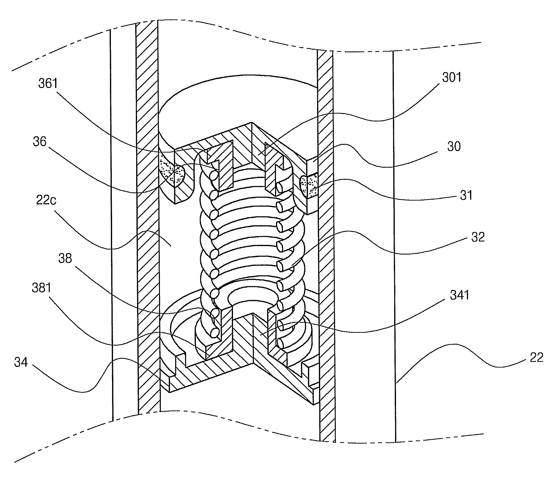
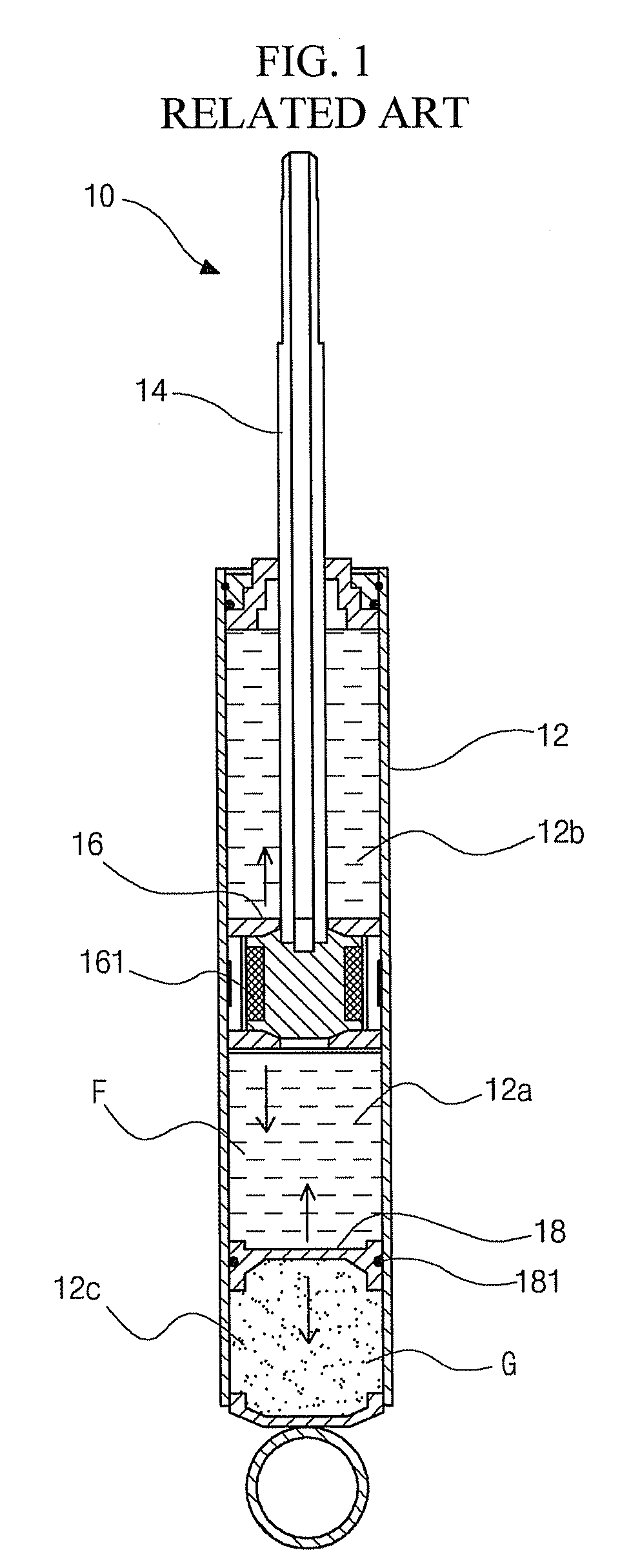
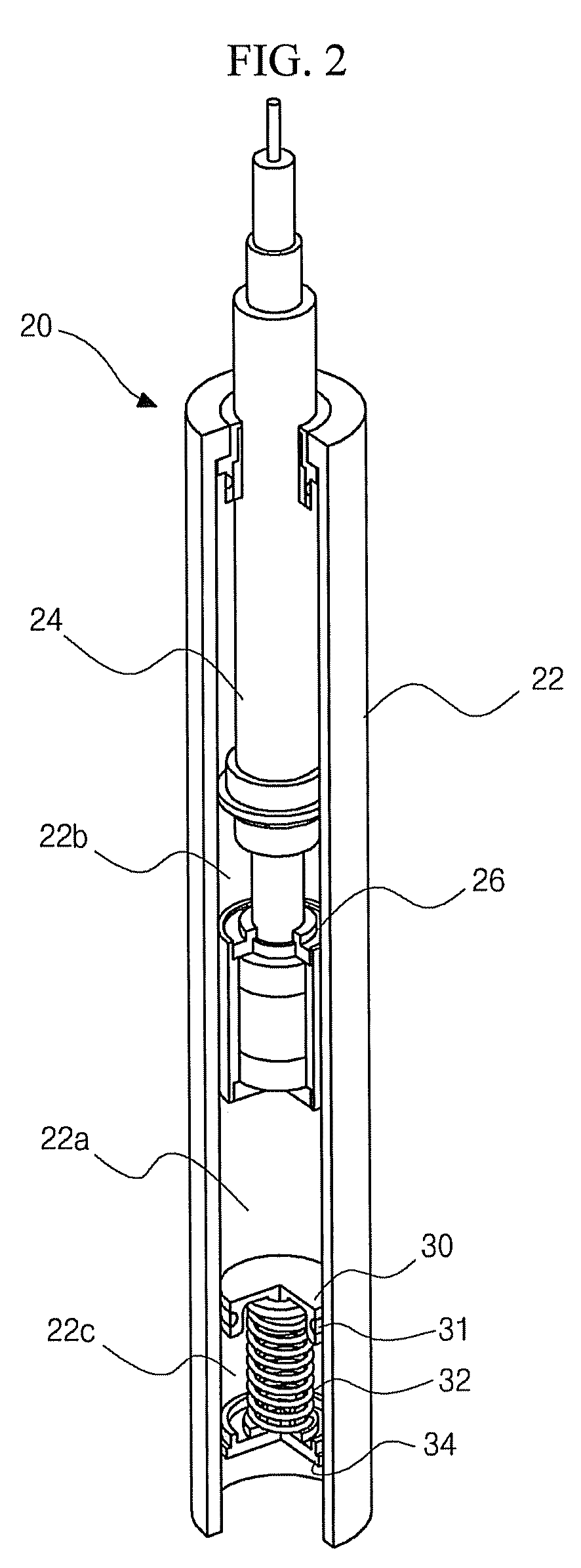
[0037]FIG. 2 is a perspective cut view illustrating a structure of a damper for continuously variably adjusting a damping force according to an embodiment of the present invention, and FIGS. 3 and 4 are perspective cut view and perspective exploded view, respectively, illustrating a structure of a major portion of the damper of FIG. 2.

[0038]Referring to FIGS. 2 to 4, the damper 20 according to the embodiment of the present invention includes a cylinder 22, a piston rod 24 that is inserted into the cylinder 22 and moves back and forth, a piston valve 26 that is coupled to a bottom portion of the piston rod 24 and moves back and forth in the cylinder 22 according to the movement of the piston rod 24, a MR fluid that fills the cylinder 22 and moves between an intension space 22b over the piston valve 26 and a compression space 22a below ...


PUM


Abstract

Disclosed is a damper for continuously variably adjusting a damping force that includes: a cylinder; a piston rod that is inserted into the cylinder and moves back and forth; a piston valve that is coupled to a bottom portion of the piston rod and moves back and forth in the cylinder according to the movement of the piston rod; a MR fluid that fills the cylinder and moves between a tension space over the piston valve and a compression space below the piston valve; and a volume compensation means that is located in the cylinder and compensates for a volume change of an inner space of the cylinder due to the movement of the piston rod, the volume compensation means including: a floating plunger that is configured to be below the piston valve and capable of moving up and down; a coil spring that is coupled to a bottom surface of the floating plunger and supports the floating plunger; and a support cup that is fixed onto the cylinder, coupled to a bottom portion of the coil spring to support the coil spring, and forms a buffer space, along with the floating plunger, between the support cup and the floating plunger.

Description

[0001]This application claims the benefit of Korean Patent Application Nos. 10-2009-0033068 and 10-2010-0023181 filed on Apr. 16, 2009 and Mar. 16, 2010, respectively, which are hereby incorporated by reference.BACKGROUND OF THE INVENTION[0002]1. Field of the Invention[0003]The present invention relates to a damper for continuously variably adjusting a damping force, and more particularly, to a damper for continuously variably adjusting a damping force for vibration occurring when driving on road.[0004]2. Discussion of the Related Art[0005]Generally, a suspension is equipped between a vehicle body and a vehicle wheel in order to improve ride comfort. The suspension includes a chassis spring that absorbs vibration and shock due to a road surface, and a damper that damps free vibration of the chassis spring in order to improve ride comfort.[0006]The damper functions to absorb and quickly damp the vibration of the chassis spring.[0007]Recently, an active control type suspension is wide...

Claims


Application Information

Patent Timeline
Patent Type & Authority Patents(United States)
IPC IPC(8): F16F9/53
CPCF16F9/067F16F9/53
Inventor LEE, DONG-RAKCHIN, MIN-HO
Owner S&T DAEWOO
Learn More