
Generating unit comprising a combustion engine and a generator

a technology of generating unit and combustion engine, which is applied in the direction of engine-driven generator propulsion, electric vehicles, dynamo-electric machines, etc., can solve the problems of short tolerance chain and short lines of force, and achieve the effect of short tolerance chain, easy assembly and access, and add to the stiffness of the cranksha

Active Publication Date: 2012-07-24
STEYR MOTORS BETRIEBS GMBH
View PDF13 Cites 7 Cited by
  • Summary
  • Abstract
  • Description
  • Claims
  • Application Information

AI Technical Summary

Benefits of technology

This configuration minimizes bulk and weight, provides precise guidance for the rotor, and allows for efficient power conversion with reduced vibration and thermal expansion issues, making it suitable for high-power applications in vehicles.

Problems solved by technology

This results in very short lines of force and a very short tolerance chain.

Method used


Image

  • Generating unit comprising a combustion engine and a generator
  • Generating unit comprising a combustion engine and a generator

Examples


Embodiment Construction

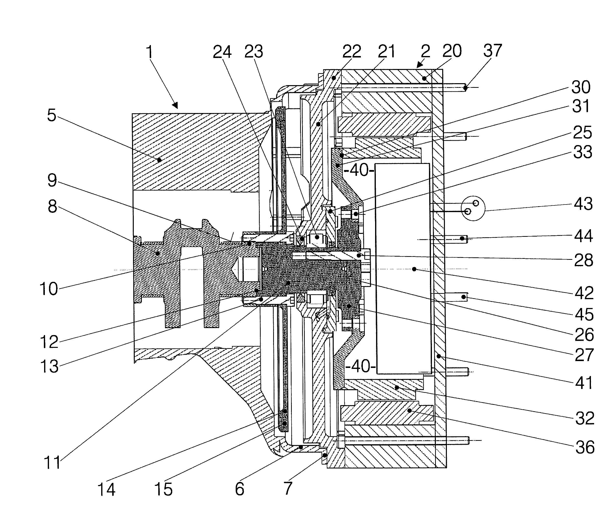
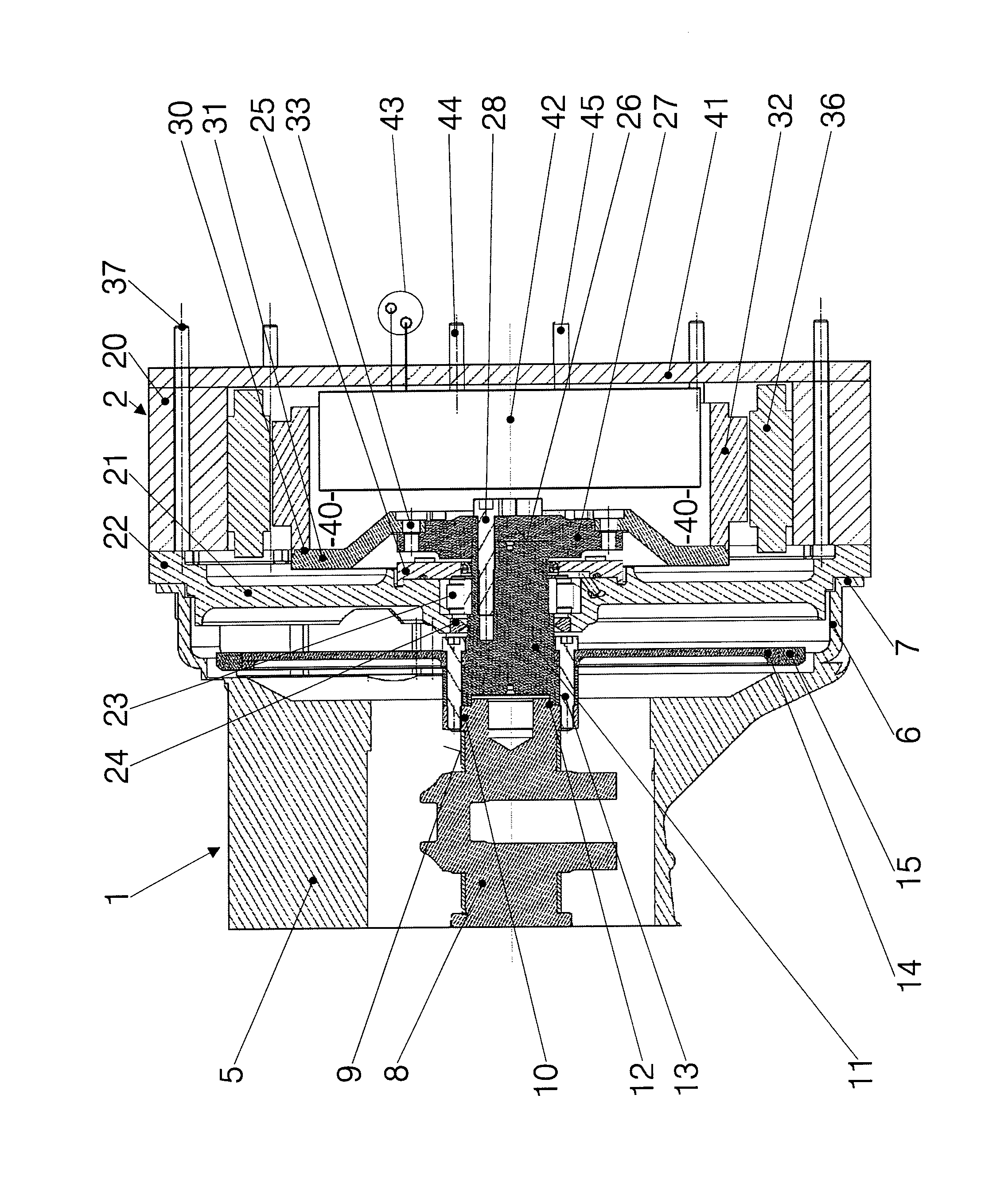
[0012]The unit consists of a combustion engine, generally referenced as 1, and a generator 2. Of the first (1), part of the crankcase 5 and the crankshaft 5 are visible. The crankcase 5 widens into a coupling bell 6 ending in a gearbox flange to which a gearbox is fitted in conventional systems. The crankshaft is supported by a number of bearings and end in an end piece 10 outside the outermost bearing 9. In conventional units, a clutch would be fitted to the end piece 10.

[0013]In the disposition according to the invention, a stub shaft 11 is fitted to the end piece 10 for driving a generator 2. It has a centering offset 12 and its one end is rigidly connected to the crankshaft by means of screw bolts 13. In the embodiment shown, a disk 14 with a gear ring 14 for cooperating with the pignon of a starter is fixed by the same screw bolts.

[0014]The casing 20 of the generator 2 has, on its side facing the combustion engine, a front plate 21, the outer rim of which forms a centering flan...


PUM


Abstract

A power generating unit consists of an internal combustion engine (1) and a generator (2), the former comprising a crankshaft (8) received in a crankcase (5) and the generator comprising a generator housing (20) connected to the crankcase (5), a stator (36) and a rotor (30) that is connected so as to rotate with the crankshaft (8). The aim is to provide a power generation unit that requires little space and that allows a precise guidance of a rotor designed for the overall unit power. A concentric stub shaft (11) is fixedly connected at the one end to the crankshaft (8) and at the other end to the rotor (30). The generator housing (20), on its side facing the internal combustion engine (1), has a front plate (21) that accommodates a bearing (23) for the sub shaft (11). The rotor (30) is otherwise overhung.

Description

BACKGROUND OF THE INVENTION[0001]The invention pertains to a generating unit comprising a combustion engine and a generator, the combustion engine having a crankshaft journalled in a crankcase and the generator comprising a generator casing joined to the crankcase, a stator and a rotor coupled to the crankshaft. The generator unit can be a stationary standby unit or a drive unit for a vehicle with electric motors, in particular wheel-mounted motors, supplied by the generator.[0002]In such units, the whole power of the combustion engine is converted into electric power. Accordingly, the dimensions of the generator and the mass of its rotor are substantial. The first increases the weight and bulk of the whole unit, the second makes the unit prone to dynamic interaction between the rotor and the crankshaft. Such units usually employ combustion engines of high power and high specific power. Therefore and in order to allow for the small magnetic gap required for high efficiency of the ge...

Claims


Application Information

Patent Timeline
Patent Type & Authority Patents(United States)
IPC IPC(8): H02K7/18F01D15/10F02C6/00H02P9/04
CPCF02B63/04H02K7/003H02K7/006H02K7/1815B60L11/14H02K7/085F02B63/042Y02T10/641Y02T10/7077Y02T10/70B60L50/16Y02T10/64Y02T10/7072
Inventor ASCHABER, MICHAELPOXHOFER, MARKUSLEIMINGER, ANTON
Owner STEYR MOTORS BETRIEBS GMBH
Learn More