
Battery system with relays

a battery system and relay technology, applied in battery/fuel cell control arrangement, safety/protection circuit, cell components, etc., to achieve the effect of reliably cutting off excessive battery current, and reliable cutting o

Active Publication Date: 2012-07-24
SANYO ELECTRIC CO LTD
View PDF6 Cites 24 Cited by
  • Summary
  • Abstract
  • Description
  • Claims
  • Application Information

AI Technical Summary

Benefits of technology

This solution allows for reliable and safe cut-off of excessive battery current without fusing relay contacts and avoids unnecessary activation of internal current cut-off sections, ensuring reliable operation and safety.

Problems solved by technology

This is because the battery system described above establishes a delay time between excessive battery current detection and ON to OFF switching of the relays.

Method used


Image

  • Battery system with relays
  • Battery system with relays
  • Battery system with relays

Examples


Embodiment Construction

)

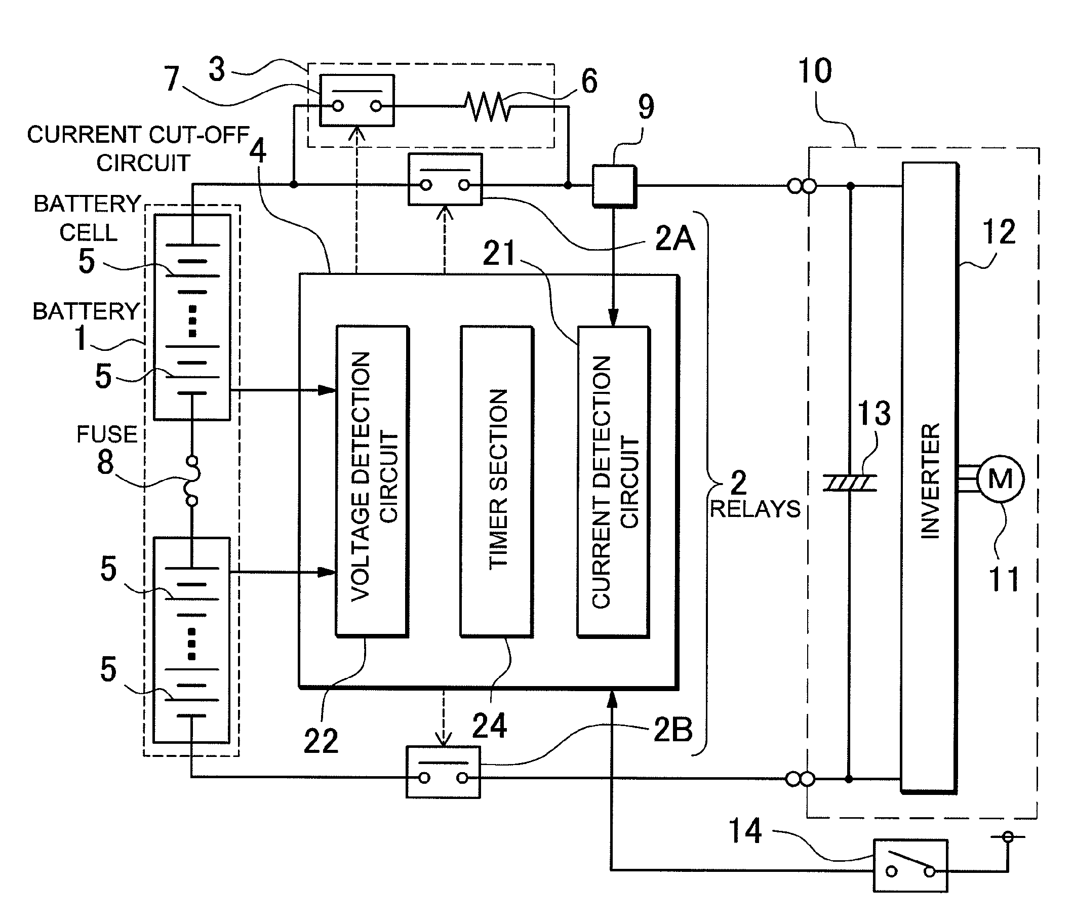
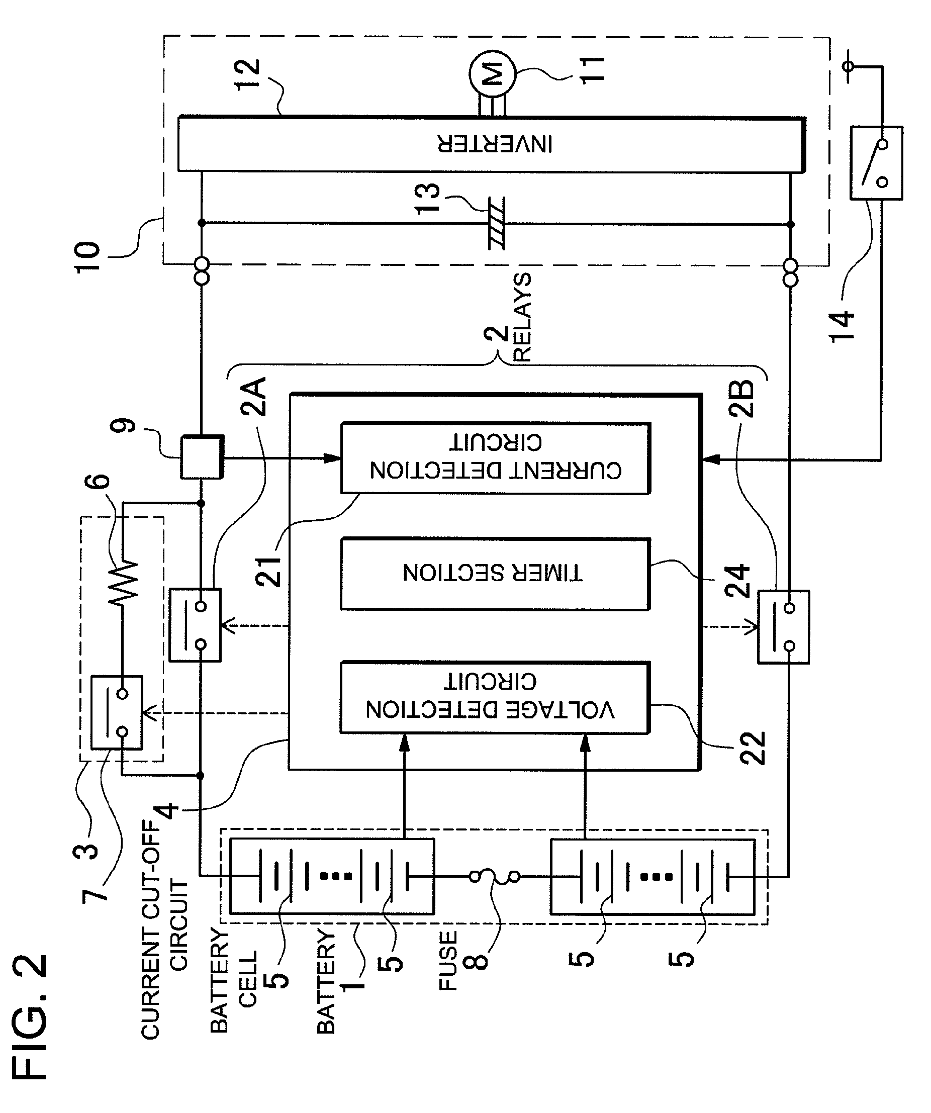
[0015]Another battery system is provided with a battery 1 having a plurality of battery cells 5 that can be recharged, a fuse 8 connected in series with the battery 1 that is self-fusing with excessive current flow, and internal current cut-off sections established in the battery cells 5 that cut-off battery cell 5 internal circuit connections under excessive current or over-charging conditions. The fusing characteristics of the fuse 8 are set to blow the fuse 8 at a current that is lower than the cut-off current of the internal current cut-off sections. In this battery system, when excessive current flows in the battery 1, the fuse 8 blows before internal current cut-off section activation.

[0016]Still another battery system is provided with a battery 1 having a plurality of battery cells 5 that can be recharged, relays 2 connected in series with the output-side of the battery 1, a current cut-off circuit 4 that detects excessive battery 1 current and controls the relays 2 from ON ...


PUM

PropertyMeasurementUnit
output voltageaaaaaaaaaa
currentaaaaaaaaaa
output voltageaaaaaaaaaa

Abstract

The battery system is provided with a battery 1 that can be recharged, a fuse 8 connected to the battery 1 that blows with excessive current flow, relays 2 connected to the output-side of the battery 1, and a current cut-off circuit 4 that detects excessive battery 1 current and controls the relays 2. The current cut-off circuit 4 detects excessive battery 1 current, and is provided with a timer section 24 that designates a time delay until the relays 2 are switched from ON to OFF. For the delay time of the timer section 24, the fusing current of the fuse 8 is set lower than the maximum cut-off current of the relays 2 and higher than the maximum allowable battery 1 charging and discharging current. In a situation where excessive current greater than the maximum cut-off current of the relays 2 flows through the battery 1, the fuse 8 is blown during the timer 24 delay time, and the current cut-off circuit 4 switches the relays 2 from ON to OFF when the delay time has elapsed.

Description

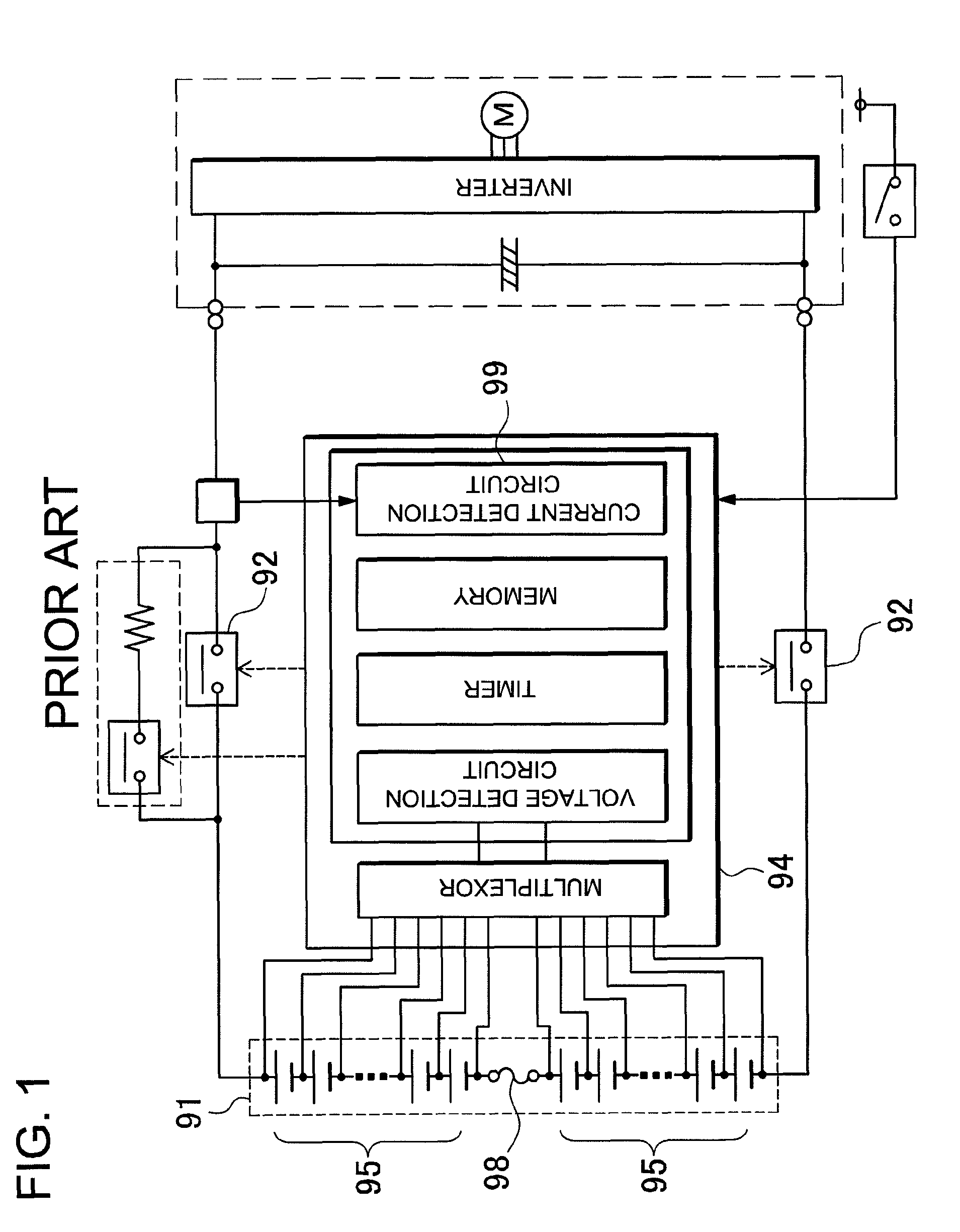
BACKGROUND OF THE INVENTION[0001]1. Field of the Invention[0002]The present invention relates to a battery system optimized for a car power source apparatus that supplies electric power to a motor that drives the vehicle, and in particular to a battery system that detects excessive current and cuts-off current flow with a fuse and relays.[0003]2. Description of the Related Art[0004]A battery system has been developed with a series connected fuse and relays to prevent excessive battery current. (Refer to Japanese Patent Application Disclosure 2008-193776.) As shown in FIG. 1, the battery system of Japanese Patent Application 2008-193776 has a battery 91 divided into two battery blocks 95, and those battery blocks 95 are connected in series via a fuse 98. In addition, the battery system has relays 92 connected to the output-side of the battery 91. In this battery system, if excessive current flows in the driving battery, the fuse 98 blows and cuts-off battery 91 current. Furthermore, ...

Claims


Application Information

Patent Timeline
Patent Type & Authority Patents(United States)
IPC IPC(8): H02J7/00H01M50/583H01M50/588H01M50/59
CPCB60L3/0046H02H9/001H02J7/0026B60L3/0069B60L3/04B60L11/1803B60L11/1862B60L11/1864B60L3/0053Y02T10/7055Y02T90/34B60L2240/549B60L2240/80B60L2270/20B60L2240/547Y02T10/7044Y02T10/7005Y02T10/7061Y02T10/7011B60L50/51B60L58/21B60L58/15B60L58/18H02J7/0014Y02T10/70H02J7/00302H02J7/00304H02H7/18H01H85/46Y02T90/40
Inventor FURUKAWA, KIMIHIKOYANO, JUNYATANAKA, KUNIHO
Owner SANYO ELECTRIC CO LTD
Learn More