
Liquid crystal panel, liquid crystal display, and driving method thereof

a technology of liquid crystal display and liquid crystal panel, which is applied in the direction of instruments, static indicating devices, etc., can solve the problems of long reaction time, slow reaction speed of liquid crystal material, and the inability of liquid crystal material to track the movement of objects in real time during scanning one pictur

Active Publication Date: 2012-07-24
KUSN INFOVISION OPTOELECTRONICS
View PDF10 Cites 18 Cited by
  • Summary
  • Abstract
  • Description
  • Claims
  • Application Information

AI Technical Summary

Benefits of technology

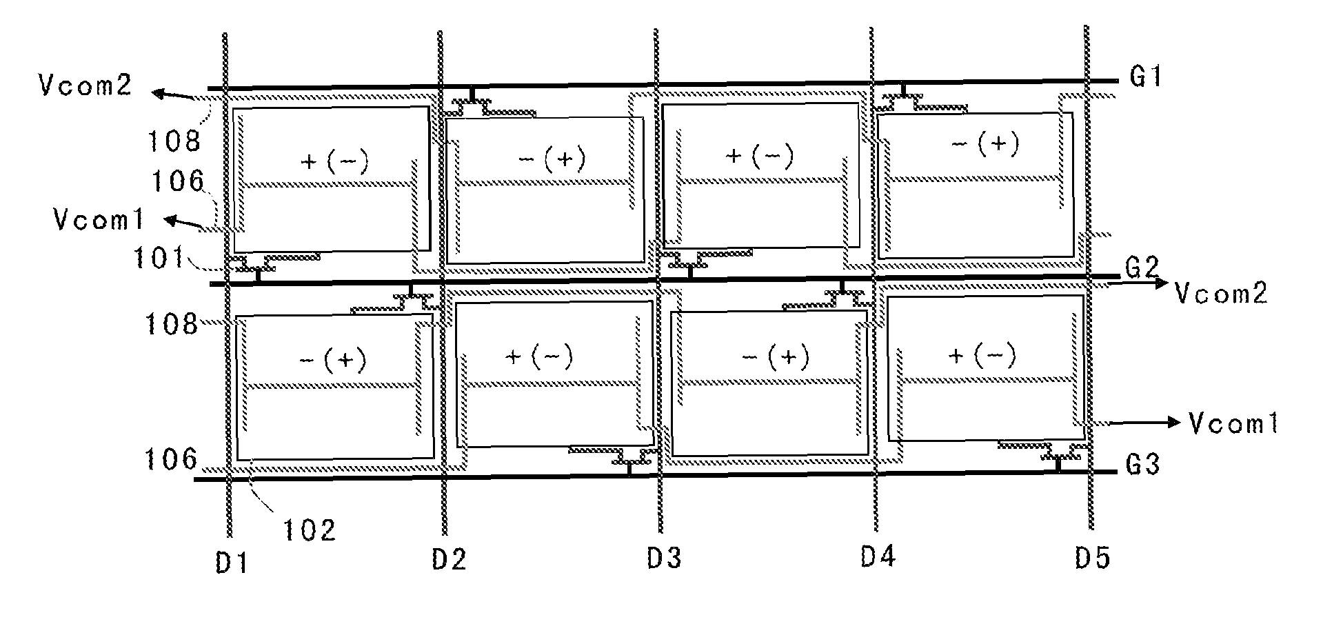
The invention provides a liquid crystal panel, display, and driving method that can perform black insertion or grey insertion processing without increasing the driving frequency and have a precharge function. The panel includes scanning lines, data lines, and pixels with a thin film transistor, a pixel electrode, and a first common electrode. The first common electrodes of first pixels are electrically connected, and the first common electrodes of second pixels are electrically connected. The driving method involves applying data signals to the data lines and inputting different common voltage signals to the first and second pixels. This technology allows for efficient processing and improved display quality.

Problems solved by technology

This is because the liquid crystal material has a slow reaction speed and long reaction time.
Moreover, when an object in the pictures moves rapidly, the liquid crystal material cannot track the movement of the object in real time during scanning one picture.
However, if the way of changing the stickiness of the liquid crystal is used to improve the quality of the dynamically displayed pictures, other parameters and characteristics of the liquid crystal will be changed accordingly, which causes other disadvantageous effects.

Method used


Image

  • Liquid crystal panel, liquid crystal display, and driving method thereof
  • Liquid crystal panel, liquid crystal display, and driving method thereof
  • Liquid crystal panel, liquid crystal display, and driving method thereof

Examples


Embodiment Construction

[0036]The exemplary embodiments will be described below in detail with reference to the accompanying drawings.

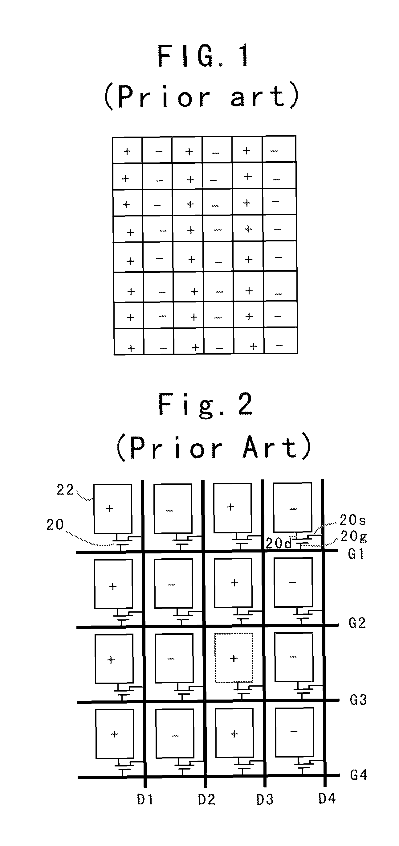
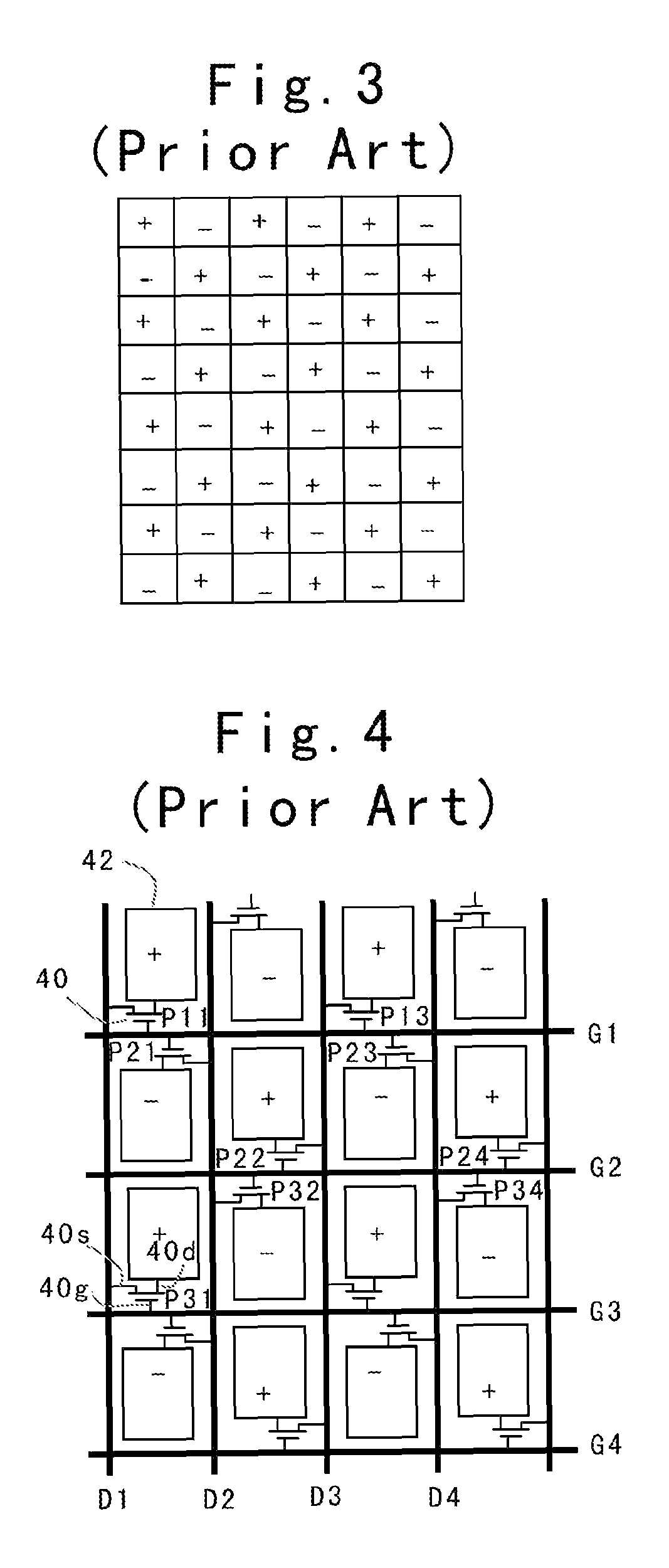
[0037]Although the following embodiments are described in detail in the case that an LCD employs dot-inversion driving, the embodiments of the invention are not limited thereto. For example, the LCD of the embodiments of the invention may also employ column-inversion driving. Any modification should be included in the protection scope of the claims of the invention so long as it does not deviate from the essence of the invention.

[0038]It will be described to the first embodiment of the invention first with reference to FIGS. 6 to 10B. The LCD of the first embodiment of the invention comprises a liquid crystal panel that includes an array substrate and a color filter substrate (also referred to as an opposite substrate).

[0039]As shown in FIG. 7, the liquid crystal panel generally includes a plurality of pixels 10, and has data lines D1, D2, D3 . . . and scanning lines G1, G2,...


PUM


Abstract

A liquid crystal panel, a liquid crystal display, and a driving method thereof are disclosed. The liquid crystal panel comprises scanning lines, data lines, and a plurality of pixels, each of the plurality of pixels including a TFT, a pixel electrode, a first common electrode, and a second common electrode. The first common electrodes of first pixels of the plurality of pixels are electrically connected via a first common line, the first common electrodes of second pixels of the plurality of pixels are electrically connected via a second common line, and the second common electrodes of the plurality of pixels are electrically connected.

Description

CROSS REFERENCE TO RELATED APPLICATION[0001]This application claims the benefit of priority from Chinese Patent Application No. 2008101260392 filed on Jun. 30, 2008, the entire content of which is hereby incorporated by reference.FIELD OF THE INVENTION[0002]The invention relates to the field of liquid crystal displays, and in particular to a liquid crystal panel, a liquid crystal display, and a driving method thereof.BACKGROUND OF THE INVENTION[0003]Liquid crystal displays (LCDs) have found wide applications in modern electronic devices such as personal computer screens, liquid crystal televisions, cell phones or Personal Digital Assistants (PDAs) due to their advantageous characteristics of low power consumption, light weight, thin profile, etc.[0004]In general, an LCD controls light transmittance of liquid crystal by an electrical field so as to display images. In terms of the electrical field's driving direction, liquid crystals can be roughly sorted into a horizontal electrical ...

Claims


Application Information

Patent Timeline
Patent Type & Authority Patents(United States)
IPC IPC(8): G09G3/36
CPCG09G3/3648G09G3/3614G09G2300/0426G09G2300/0876
Inventor CHUNG, TE-CHENLIAO, CHIA-TECHIU, YU-WEN
Owner KUSN INFOVISION OPTOELECTRONICS
Learn More