Supercharge Your Innovation With Domain-Expert AI Agents!

Projection illumination system

Active Publication Date: 2012-07-24
CARL ZEISS SMT GMBH
View PDF33 Cites 9 Cited by
  • Summary
  • Abstract
  • Description
  • Claims
  • Application Information

AI Technical Summary

Benefits of technology

The present invention provides a projection illumination system with an interferometer arrangement for measuring parameters of individual components of the system and changes over time of these parameters. The interferometer arrangement allows for the acquisition of parameters during an exposure operation of the system without impairing the operation. The measuring radiation is incident onto the optical components in an inclined way, and the extended region of the optical surface onto which the measuring radiation beam is directed is a relatively large portion of more than 10% of the surface of the optical component effective for the projection radiation. The interferometer arrangement includes a measuring radiation source, beam forming optics, a back reflector with a diffraction grating, and a two-dimensional positionally resolving detector. The system can acquire parameters of the optical components during the exposure operation of the system without impairing the operation.

Problems solved by technology

Due to the large number of optical components in a projection illumination system, the imaging quality is determined by a multitude of parameters of the optical components and is also subject to operation related drifts.

Method used


Image

  • Projection illumination system
  • Projection illumination system
  • Projection illumination system

Examples


Embodiment Construction

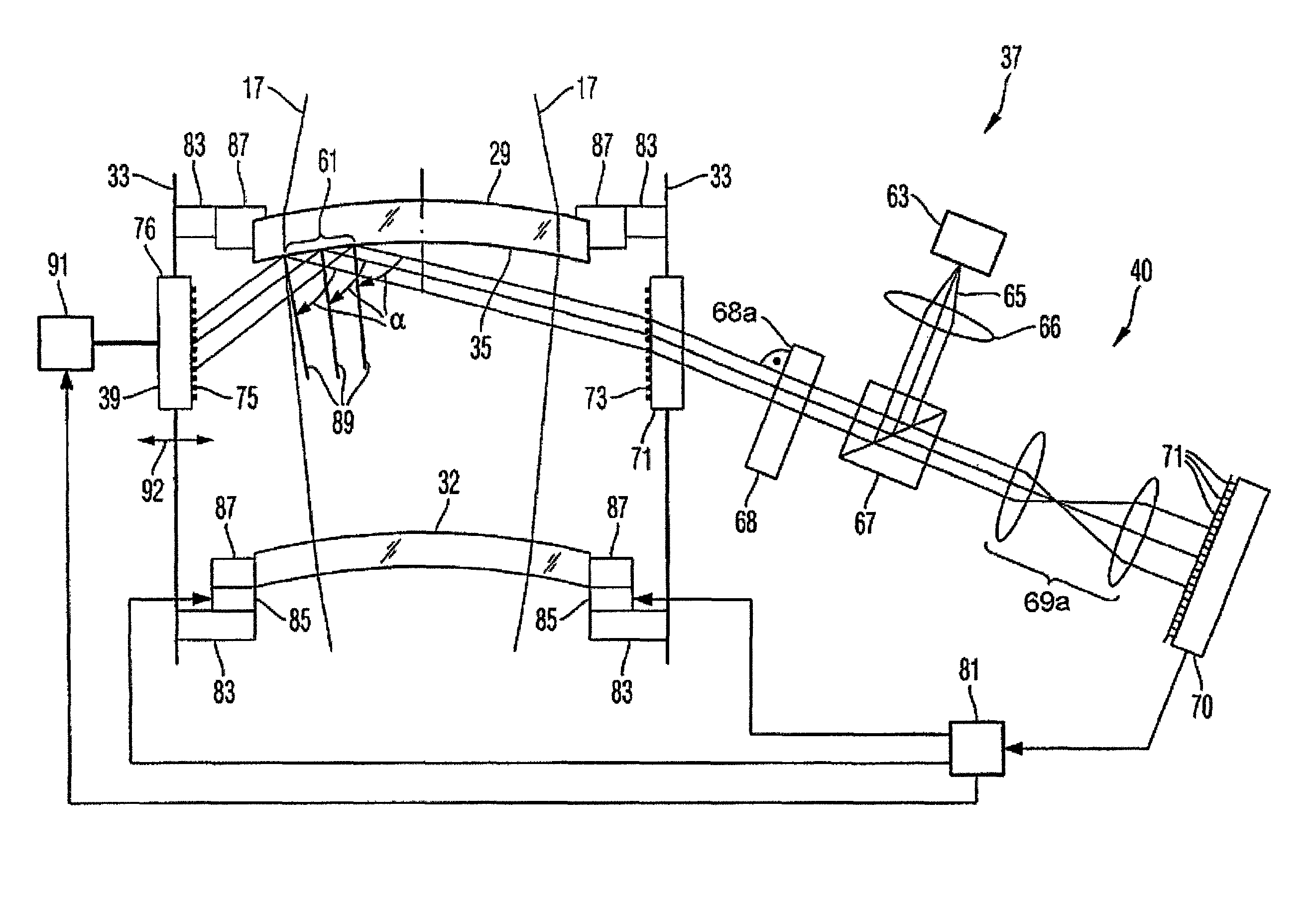
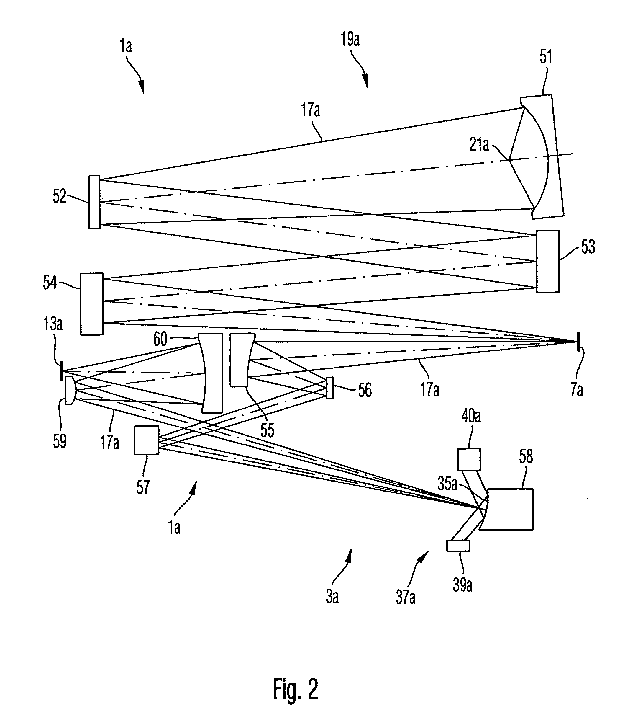
[0043]In the exemplary embodiments described below, components that are at least analogous in function and structure are designated as far as possible by like reference numerals. Therefore, to understand the features of the individual components of a specific embodiment, the descriptions of other embodiments and of the summary of the invention should be referred to.

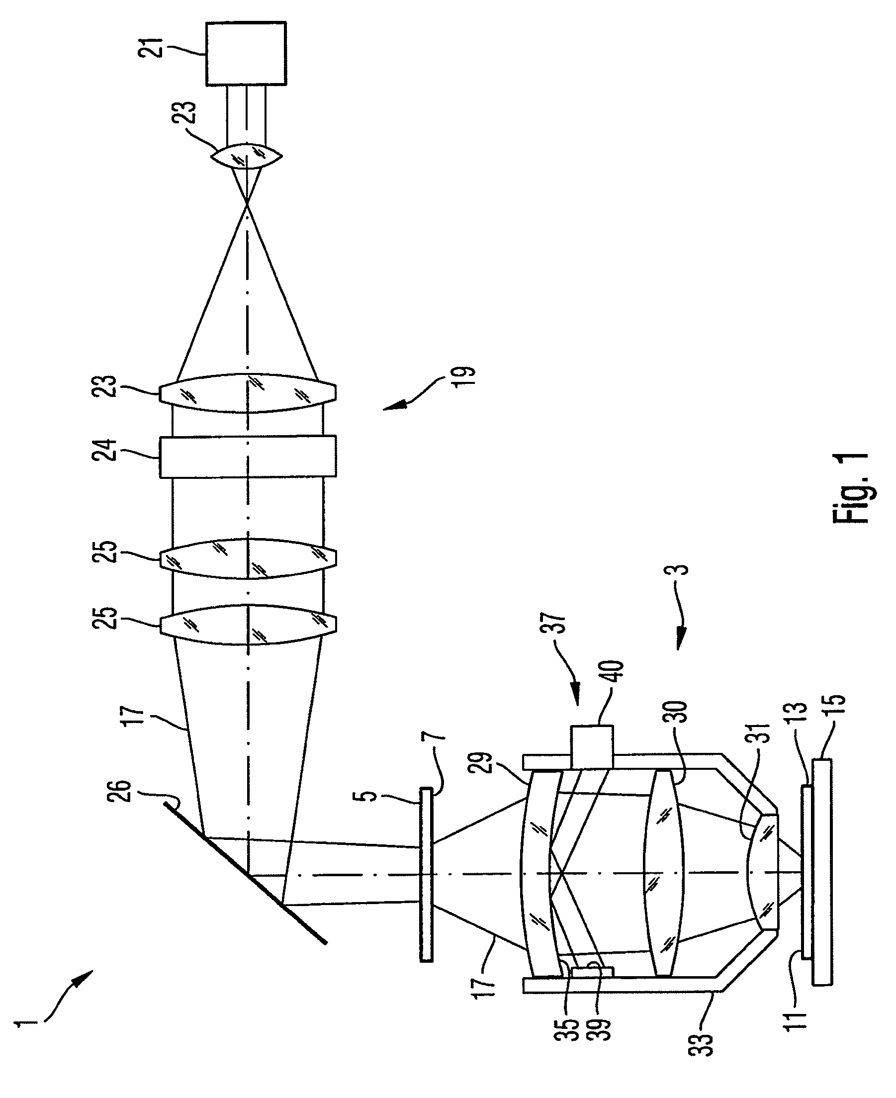
[0044]FIG. 1 shows a schematic illustration of a projection illumination system according to an embodiment of the invention. The projection illumination system 1 comprises a projection optics 3 for imaging a photo mask 7 provided on a mask holder 5 to a surface 11 of a semiconductor wafer 13 covered with photoresist, wherein the semiconductor wafer is held on a wafer table 15.

[0045]The mask 7 is exposed with projection radiation 17 which is generated by an illumination optics 19. For generating the projection radiation, the illumination optics 19 comprises a radiation source 21, for example a KrF-Excimer laser, which gene...


PUM


Abstract

A projection illumination system with a plurality of optical components (29, 32) includes an interferometer arrangement (37) whose components are arranged outside a projection beam path (17) of the projection illumination system. Measurement radiation of the interferometer arrangement strikes a surface (35) of the optical component (29) to be measured under a large angle of incidence (α). Actuators (83, 87) of the projection illumination system can be actuated as a function of a measurement radiation intensity distribution detected using the interferometer arrangement in order to change imaging characteristics of the projection illumination system and to keep them stable in particular also with respect to drifting.

Description

[0001]This application is a Continuation of International Application No. PCT / EP2006 / 011419, filed Nov. 28, 2006, which was published under PCT Article 21(2) in the German language and which claims priority to German Application No. 10 2005 056 914.5, filed Nov. 29, 2005. These Applications, in their entirety, are incorporated herein by reference.BACKGROUND OF THE INVENTION[0002]1. Field of the Invention[0003]The invention relates to a projection illumination system.[0004]Lithographic methods are conventionally employed for the manufacturing of miniaturized structures and components. Miniaturized components and structures include, for example, integrated circuits, fluid crystal elements, micromechanical components and the like. Hereby, patterns or structures predetermined on a mask (“reticle”) are imaged onto a radiation sensitive substrate, such as, for example, a wafer provided with a radiation sensitive layer (“resist”), by an imaging optics of a projection illumination system. T...

Claims


Application Information

Patent Timeline
Patent Type & Authority Patents(United States)
IPC IPC(8): G03B27/42G03B27/54
CPCG03F7/706
Inventor FREIMANN, ROLFPHILIPPS, JENS
Owner CARL ZEISS SMT GMBH
Features
  • R&D
  • Intellectual Property
  • Life Sciences
  • Materials
  • Tech Scout
  • Unparalleled Data Quality
  • Higher Quality Content
  • 60% Fewer Hallucinations
Learn More