
Inverted microscope for high-contrast imaging

a high-contrast, microscope technology, applied in the field of inverted microscopes, can solve the problems of increasing complexity and cost, unable to provide the desired result for special cases, and aforementioned contrasting process is generally incompatible with each other

Active Publication Date: 2012-07-24
LEICA MICROSYSTEMS CMS GMBH
View PDF15 Cites 8 Cited by
  • Summary
  • Abstract
  • Description
  • Claims
  • Application Information

AI Technical Summary

Benefits of technology

[0014]It is an aspect of the present invention to provide, in the case of an inverted microscope of the type mentioned at the outset, various contrasting processes which do not require complex adjustment even when changing the objective. It is an additional, alternative aspect of the present invention to allow automated selection of the modulators required for a contrasting process in accordance with the selected objective.

Problems solved by technology

That is to say, a flexible response would require the provision of a large number of special objectives, and this increases both complexity and costs.
In practice, conventional special objectives are therefore universally usable standard solutions which in many cases cannot provide the desired result for special cases.
Starting from the problem that the modulators required for phase and relief contrast are arranged in the objective pupil and therefore in the usually inaccessible interior of an objective, the aforementioned contrasting processes are generally incompatible with each other.
The flexibility of this solution is therefore also limited.
On account of the need, in the case of the solution of CH-294755, to have to monitor both centering and focusing by means of auxiliary optics in the event of any alteration of the position of the pupil when changing the objective, this approach is impractical.

Method used


Image

  • Inverted microscope for high-contrast imaging
  • Inverted microscope for high-contrast imaging
  • Inverted microscope for high-contrast imaging

Examples


Embodiment Construction

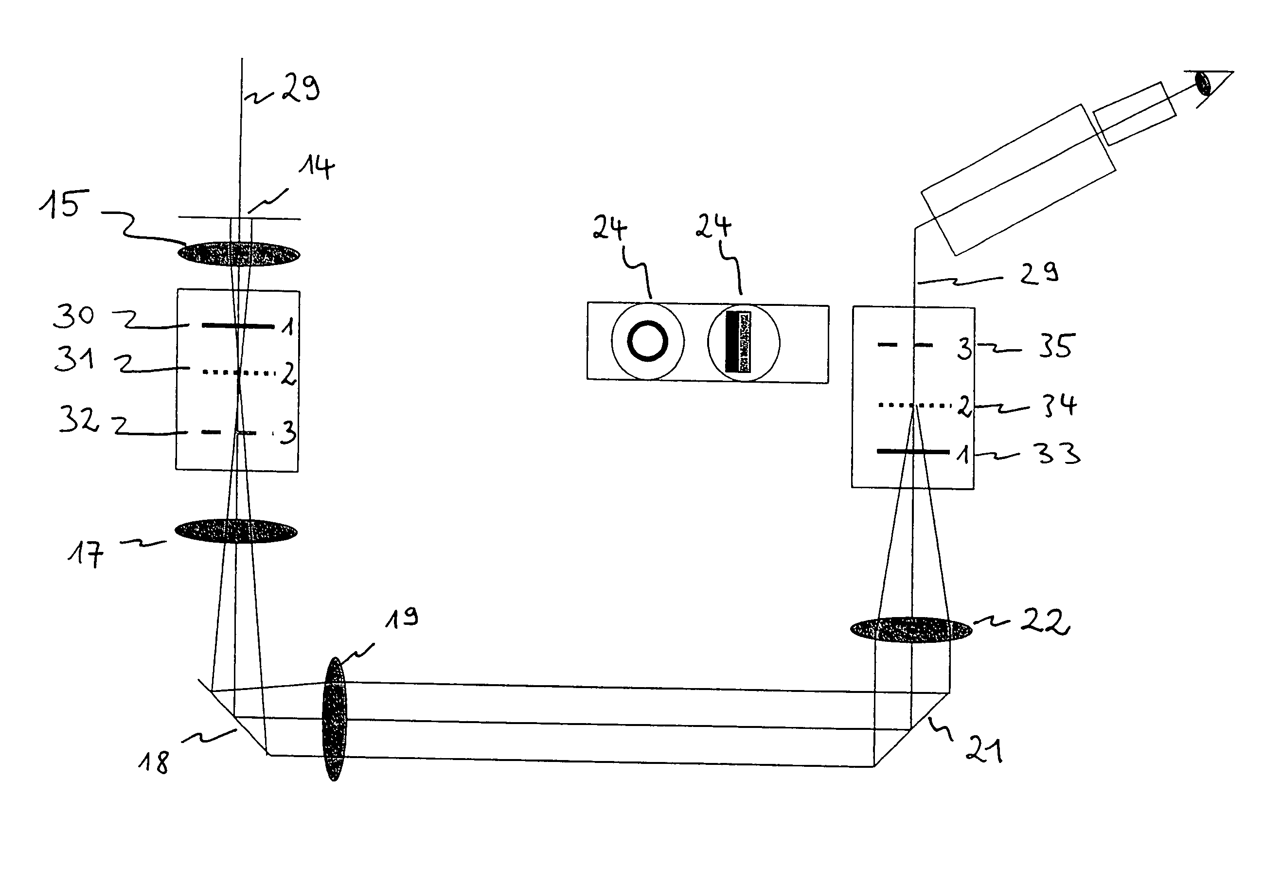
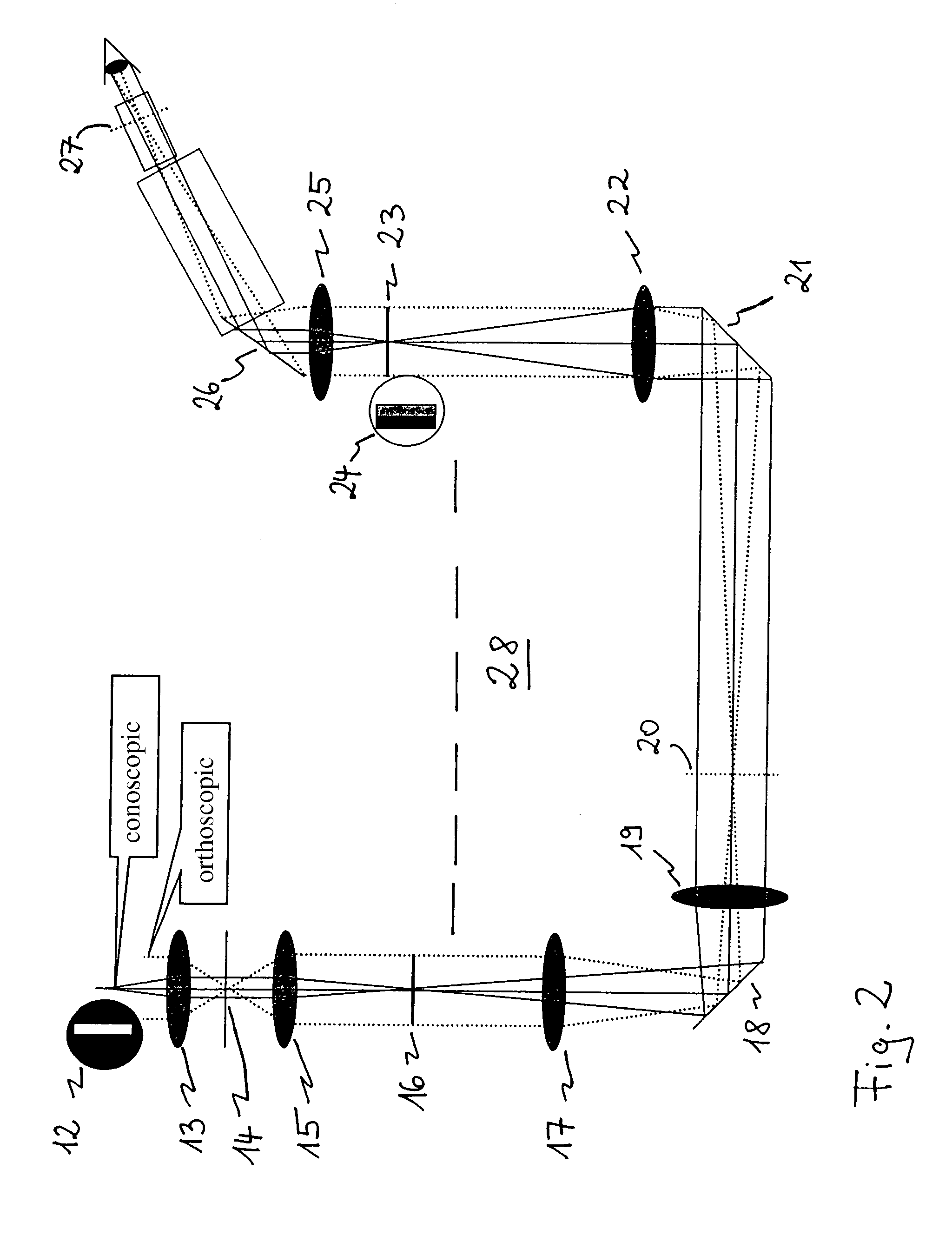
[0024]In an embodiment, the present invention provides a device with which, for a plurality of objectives to be selected, suitable modulators can be arranged at the associated locations of the respective intermediate images of the objective pupils, referred to hereinafter as intermediate pupils. This allows rapid changeover of the modulator of a specific contrasting process as a function of the respectively used objective with the associated intermediate pupil. The modulators are arranged at the freely accessible locations of the intermediate pupils, thus obviating the need for special objectives.

[0025]The device according to the invention not only allows the modulators to be adapted to the respectively used objectives; simple changeover between various contrasting processes is also possible. For this purpose, the corresponding modulators may be exchanged at the location of the intermediate pupil. Furthermore, use may also be made of modulators customised to a specific type of sampl...


PUM


Abstract

An inverted microscope for the high-contrast imaging of objects includes multiple objectives configured to be disposable in an imaging beam path. Each objective has a respective objective pupil associated therewith. A lens system is also provided for generating respective intermediate images of the respective objective pupils. A modulator disposing device, which includes a plurality of modulators, is configured to dispose the modulators at predetermined respective locations on an optical axis corresponding to the locations of the respective intermediate images of the respective objective pupils so as to contrast an object image.

Description

CROSS-REFERENCE TO RELATED APPLICATION[0001]This is a U.S. National Phase application under 35 U.S.C. §371 of International Application No. PCT / EP2006 / 005024, filed May 26, 2006. The International Application was published in German on Dec. 6, 2007 as WO 2007 / 137598 A1 under PCT Article 21 (2).FIELD[0002]The present invention relates to an inverted microscope for the high-contrast imaging of objects.BACKGROUND[0003]Inverted microscopes are characterised in that light is passed from above through the object to be examined in a transmitted light process and in that the objectives are attached below the object stage. In the case of inverted reflected light microscopes, both the illumination and the observation are carried out through the objective from below. Reflected light microscopes of this type play a central part in mineralogy and metallurgy, whereas inverted transmitted light microscopes are frequently used for the examination or for the handling of biological samples. One advan...

Claims


Application Information

Patent Timeline
Patent Type & Authority Patents(United States)
IPC IPC(8): G02B21/14
CPCG02B21/0088G02B21/14
Inventor EUTENEUER, PETERKRUEGER, RALF
Owner LEICA MICROSYSTEMS CMS GMBH
Learn More