Optical apparatus
a technology of optical apparatus and lens barrel, which is applied in the field of optical apparatus, can solve the problems of low efficiency of lens barrel attachment, and achieve the effects of improving usability of optical apparatus, increasing attachment strength, and increasing the strength of body-side mounting unit and lens-side mounting uni
- Summary
- Abstract
- Description
- Claims
- Application Information
AI Technical Summary
Benefits of technology
Problems solved by technology
Method used
Image

Examples
first embodiment
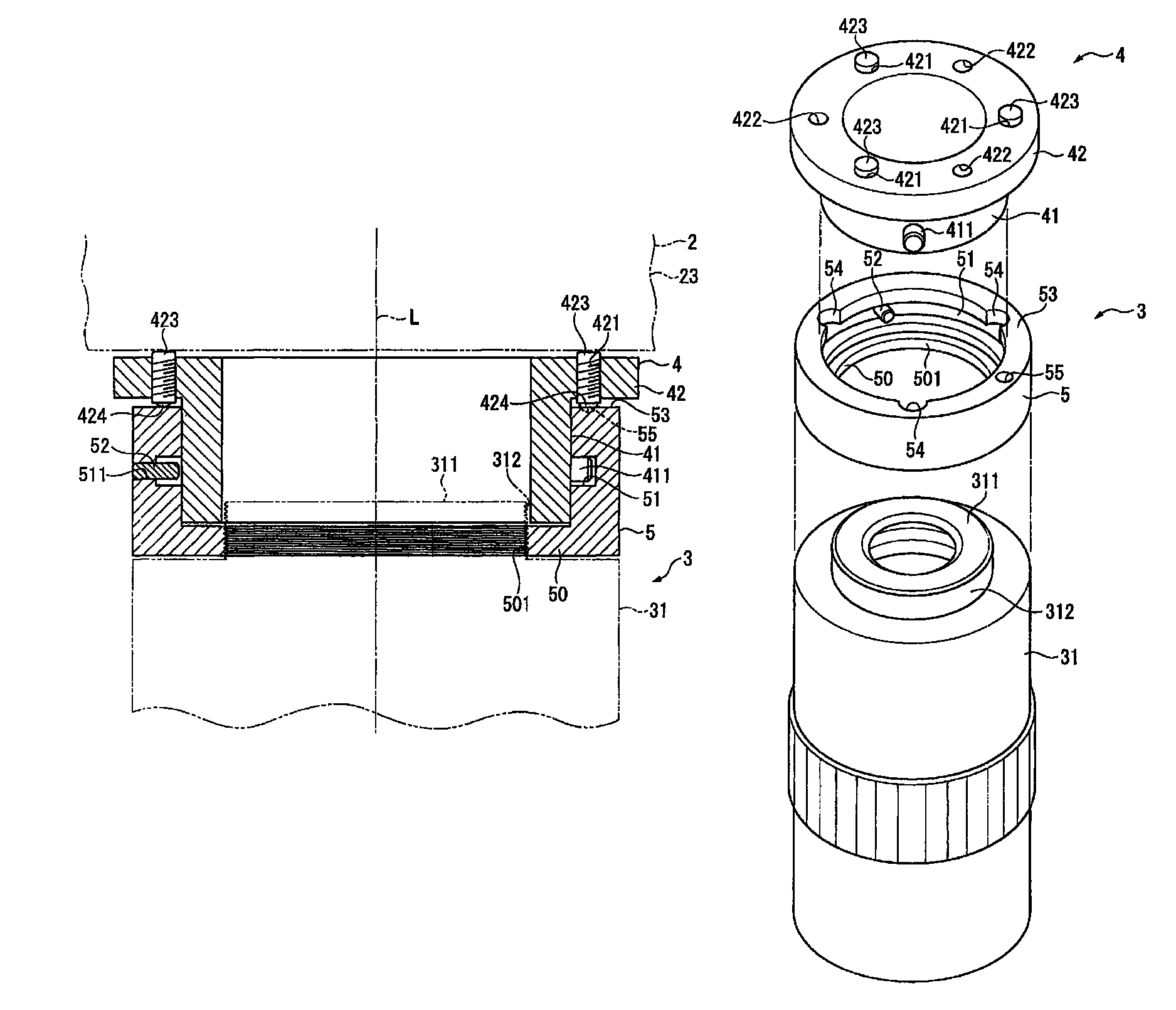
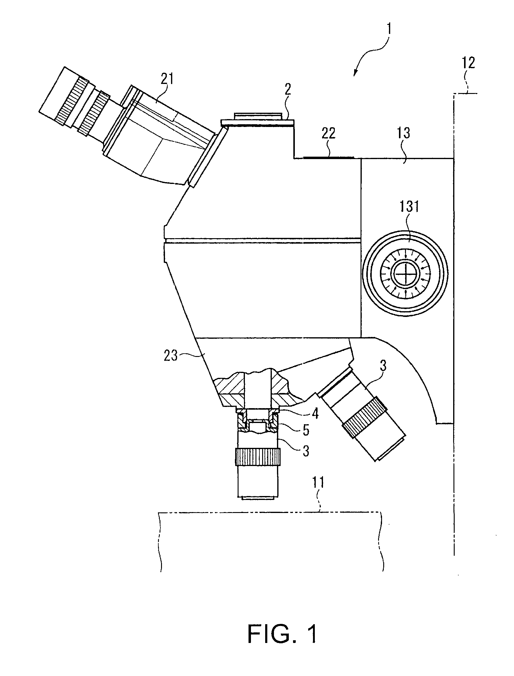
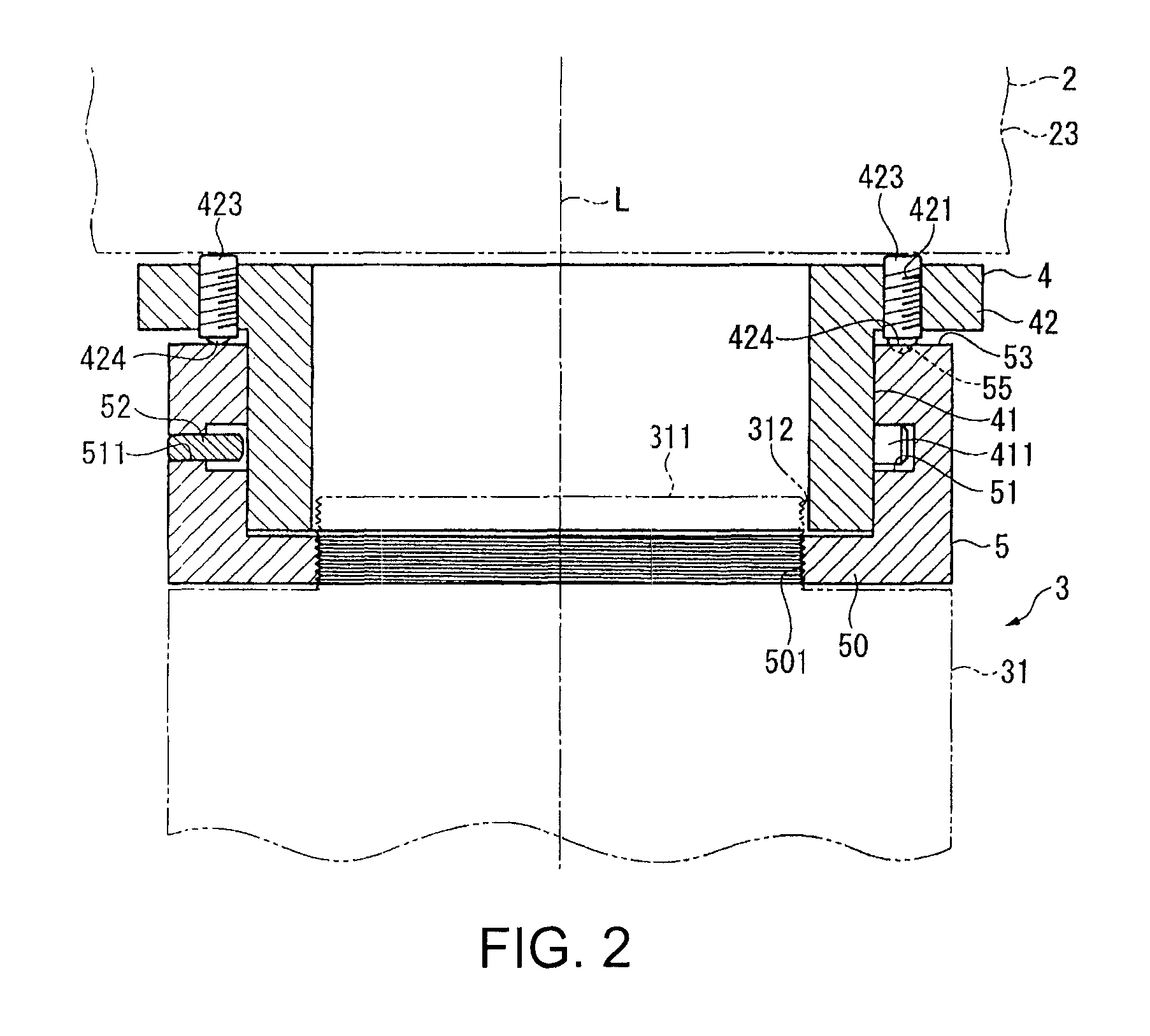
[0023]With reference to the accompanying drawings, the present invention will now be explained in detail. FIG. 1 is a general view that schematically illustrates the configuration of a microscope 1, which is an example of an optical apparatus according to the present embodiment of the invention. The microscope 1 includes a stage 11, a supporting column 12, an elevation device 13, a microscope body 2, and a plurality of lens barrels (i.e., bodytubes) 3. A measurement target object (not shown) is placed on the stage 11. The stage 11 can be moved in biaxial directions over a horizontal plane. The supporting column 12 extends in a direction perpendicular to the stage 11. The elevation device 13 can move up and down along the supporting column 12 when a knob 131 is turned. A plurality of optical components such as lenses, mirrors, prisms, and the like are provided inside the microscope body 2. The microscope body 2 is supported indirectly on the supporting column 12 with the elevation de...
second embodiment
[0045]On the other hand, an internal thread 61A is formed on the inner circumferential surface of the stiffening member 6A at a region that is in contact with the body-side mounting unit 4. The internal thread 61A is a female-screw part with which the external thread 43, that is, a male-screw part, mates. The stiffening member 6A has a flanged bottom part 62 that protrudes inward. The flanged bottom part 62 is formed at an end that is relatively remote from the body-side mounting unit 4. After the attachment of the lens barrel 3 to the body-side mounting unit 4, the stiffening member 6A having the above structure is fixed on the flange part 42A outside the lens-side mounting unit 5. The stiffening member 6A is threadably mounted on the male-screw part 43 until its bottom part 62 is brought into tight and firm contact with the protuberance part 56A. The stiffening member 6A urges the lens-side mounting unit 5 in its axial direction toward the body-side mounting unit 4. Since the lens...
PUM
 Abstract
Description
Claims
Application Information
 - R&D
- Intellectual Property
- Life Sciences
- Materials
- Tech Scout
- Unparalleled Data Quality
- Higher Quality Content
- 60% Fewer Hallucinations
Browse by: Latest US Patents, China's latest patents, Technical Efficacy Thesaurus, Application Domain, Technology Topic, Popular Technical Reports.
© 2025 PatSnap. All rights reserved.Legal|Privacy policy|Modern Slavery Act Transparency Statement|Sitemap|About US| Contact US: help@patsnap.com