
Method for transporting, erecting and replacing a nacelle including the rotor of an offshore wind turbine and watercraft for carrying out the method

Inactive Publication Date: 2012-07-31
AERODYN ENG GMBH
View PDF10 Cites 13 Cited by
  • Summary
  • Abstract
  • Description
  • Claims
  • Application Information

AI Technical Summary

Benefits of technology

[0012]The object of the invention is therefore a method for transporting and erecting a wind turbine on a foundation in an offshore area, that achieve fast restarting of the turbine in the case of repairs, so as to avoid prolonged down times and power losses.
[0014]The inventive procedure has the advantage that when using single-blade and two-blade rotors the functional unit on the watercraft due to the narrow construction can be reached the location of the offshore wind turbine without any obstructions. For example bridges and locks can be passed without any problems. Furthermore the down times of faulty offshore wind turbines and the costs associated therewith are reduced considerably since the offshore wind turbine is immediately fully operational again after the faulty unit has been replaced. Likewise the operating times for the watercraft are reduced considerably. The repair of the faulty nacelles can then be carried out in the port in the assembling hall under good working conditions with all suitable aids and tools. In the process the nacelle and the blades are completely reworked and inspected so that a turbine that is as good as new is available for the next replacement. Large components can very well fail twice during the 20 year lifetime of an offshore wind turbine.

Problems solved by technology

Large components can very well fail twice during the 20 year lifetime of an offshore wind turbine.

Method used


Image

  • Method for transporting, erecting and replacing a nacelle including the rotor of an offshore wind turbine and watercraft for carrying out the method
  • Method for transporting, erecting and replacing a nacelle including the rotor of an offshore wind turbine and watercraft for carrying out the method
  • Method for transporting, erecting and replacing a nacelle including the rotor of an offshore wind turbine and watercraft for carrying out the method

Examples


Embodiment Construction

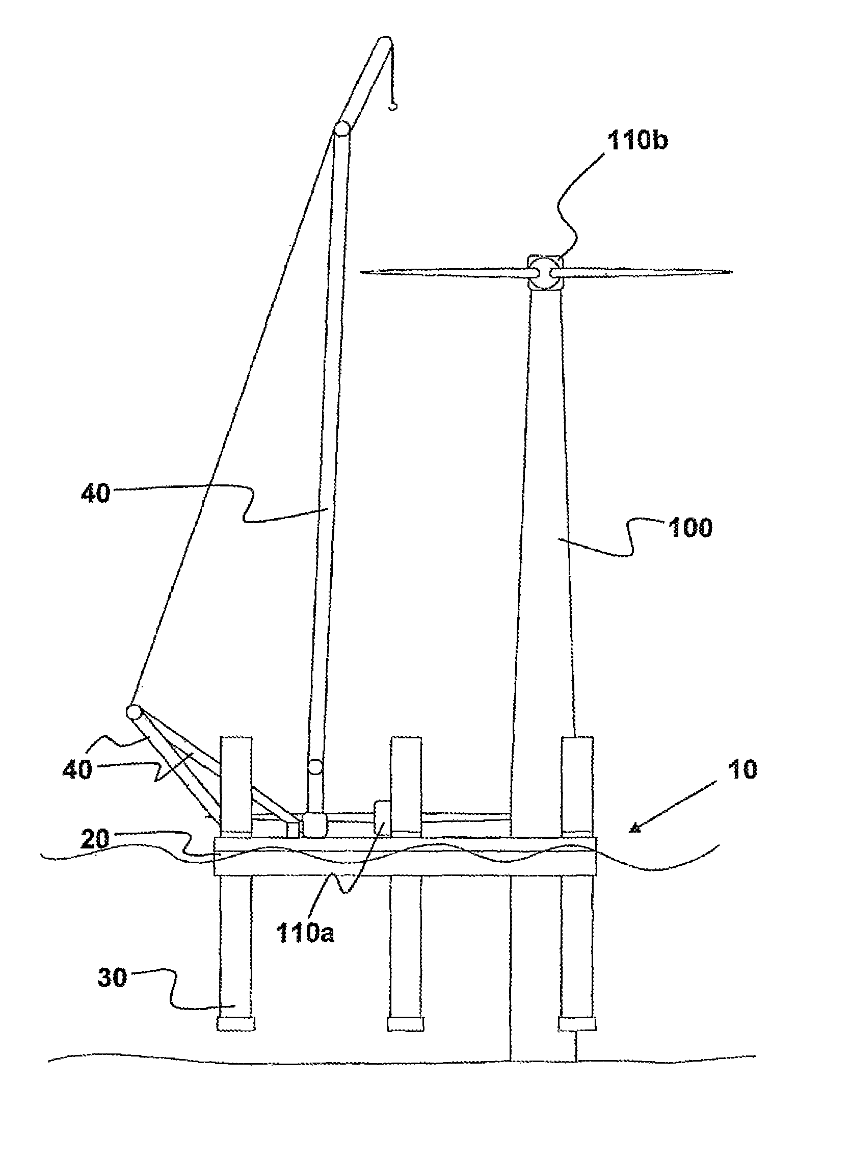
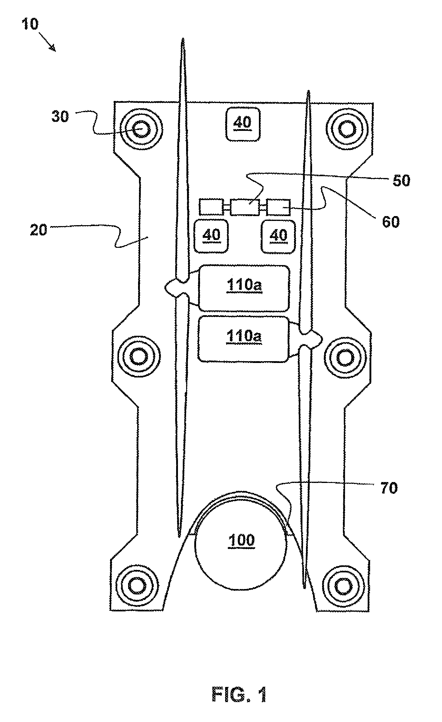
[0027]FIG. 1 shows a schematic elevation of the watercraft in a top view. For the purpose of greater clarity only those elements have been illustrated here that are directly at the level of the deck. It is thus in particular the crane superstructures that are not shown in this view.

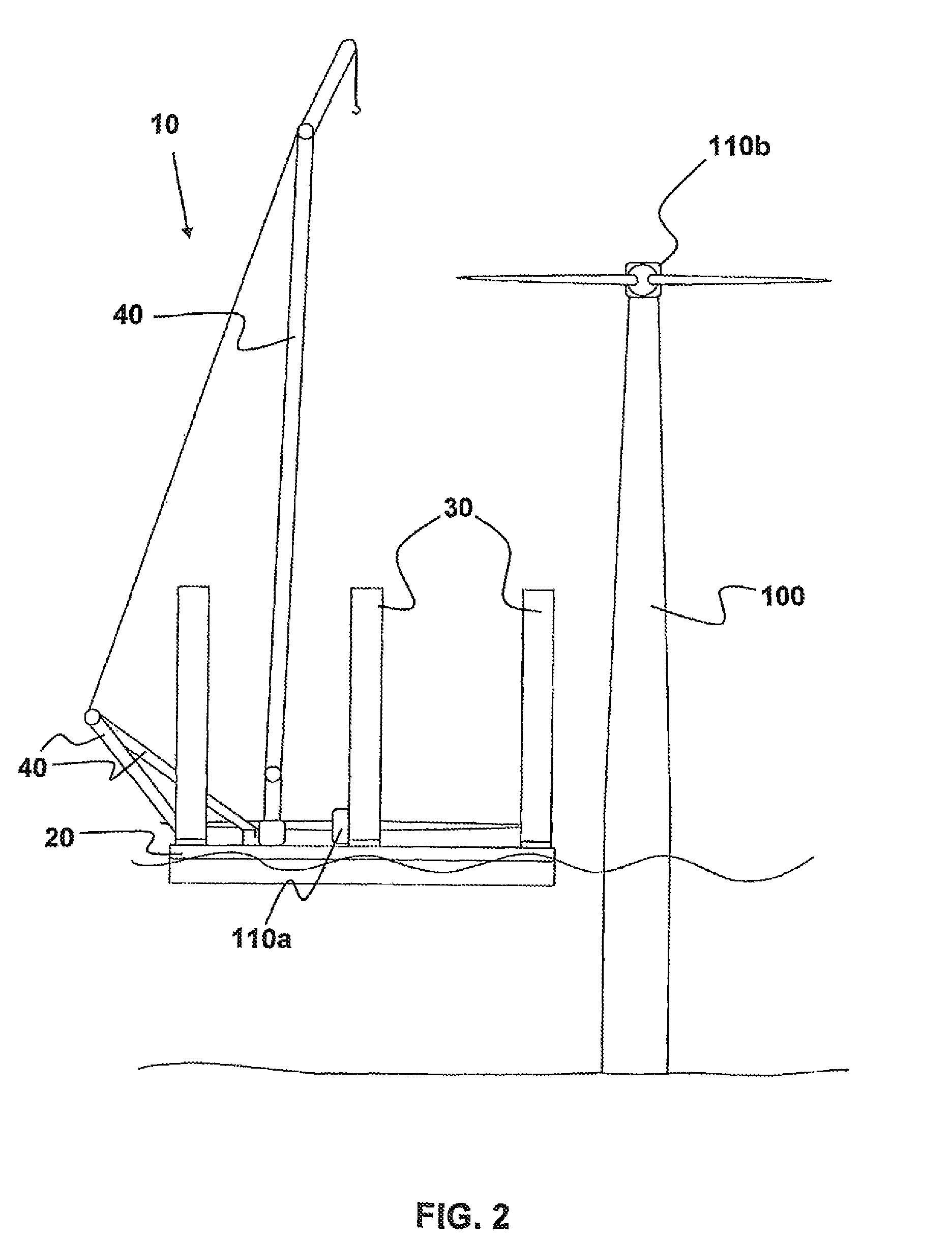
[0028]The watercraft 10 has a hull 20 with preferably six support columns 30 that can be lowered and are arranged such that a load distribution of the loads arranged on the hull results that is as even as possible. Of course it is also possible to envisage a higher or lower number of support columns 30, the minimum in terms of support columns being limited to three support columns 30.

[0029]The hull 20 has on its one end face an essentially U-shaped docking zone 70 that is arranged centrally in the longitudinal direction and that can also have an approximate V shape that is matched to the diameter of the tower of an offshore wind turbine 100 at sea level. Here the docking zone is thus arranged such that th...


PUM


Abstract

Method for installing (or replacing) a unit on the tower of an offshore wind turbine, which unit comprises a rotor including a hub and one or two rotor blades, and a nacelle receiving a gearbox and a generator. The method is characterized by pre-assembling the substantially functional unit ashore or on a platform, placing the functional unit on a watercraft in such a manner that the center of gravitation of the unit lies in the region of the longitudinal axis of the watercraft and the rotor blades extend in the longitudinal direction of the watercraft, transporting the functional unit to the site of the offshore wind turbine, lifting the functional unit from the watercraft using a crane aboard the watercraft, placing the functional unit on the tower of the offshore wind turbine, and fastening the functional unit on the tower of the offshore wind turbine.

Description

CROSS-REFERENCE TO RELATED APPLICATIONS[0001]This application represents a National Stage application of PCT / DE2008 / 000455 entitled “Method for Transporting, Erecting and Replacing a Nacelle Including the Rotor of an Offshore Wind Turbine and Watercraft for Carrying Out Said Method” filed Mar. 15, 2008, pending.BACKGROUND OF THE INVENTION[0002]The invention relates to a method for transporting and erecting or replacing a unit, formed by the nacelle and the rotor, of an offshore wind turbine. The invention further relates to a watercraft for carrying out this method.[0003]Wind power has already been known since antiquity to be used for driving machines, and nowadays it is of increasing relevance in particular for producing electrical power. The wind turbines that have evolved from the technology developed for windmills can be used at practically all sites for producing power, wind farms being installed to an increasing extent on the open sea and off the coast—that is to say offshore....

Claims


Application Information

Patent Timeline
IPC IPC(8): B63B27/00
CPCB63B35/44F03D1/001E02B17/0034E02B2017/0091F05B2230/61Y10T29/49318F05B2240/95Y02E10/727Y10T29/49316F05B2230/6102F03D13/10Y02E10/72Y02P70/50
Inventor SIEGFRIEDSEN, SONKE
Owner AERODYN ENG GMBH
Learn More