Vehicle body side structure

a technology for side structures and vehicles, applied in the direction of roofs, doors, transportation and packaging, etc., can solve the problems of increasing the complexity of the structure, and achieve the effect of simple structur

Inactive Publication Date: 2012-07-31
TOYOTA JIDOSHA KK
View PDF13 Cites 7 Cited by
  • Summary
  • Abstract
  • Description
  • Claims
  • Application Information

AI Technical Summary

Benefits of technology

[0007]The present invention has an object to provide a vehicle body side structure capable of transmitting to the pillar a load applied to the impact beam with a simple structure.
[0010]Because the end part of the impact beam is fixed to the impact beam fixing part of the impact beam extension, the impact beam is mounted to the inner panel via the impact beam extension. Because the impact beam provided with a load transmission part that extends at an angle facing the centroid of the pillar of the vehicle body from the impact beam fixing part, it is possible to reliably transmit load applied to the impact beam to the pillar centroid. Furthermore, because the load transmission part is provided on the impact beam extension and it is not necessary to have a separate member for this load transmission, complexity of the structure is avoided and it is possible to have a simple structure.
[0015]Therefore, compared to a configuration in which there is discontinuity from the impact beam fixing part up until the load transmission part, it is possible to transmit a load from the impact beam to the pillar centroid with good efficiency.
[0017]By doing this, it is possible to suppress deformation and the like of the load transmission part, and to transmit a load from the impact beam to the pillar centroid with further improved efficiency.
[0020]By the foregoing configuration, it is possible with a simple structure to transmit to the pillar a load that is applied to the impact beam.

Problems solved by technology

The additional provision of a load-transmitting member, however, increases in the complexity of the structure.

Method used


Image

  • Vehicle body side structure
  • Vehicle body side structure
  • Vehicle body side structure

Examples


first embodiment

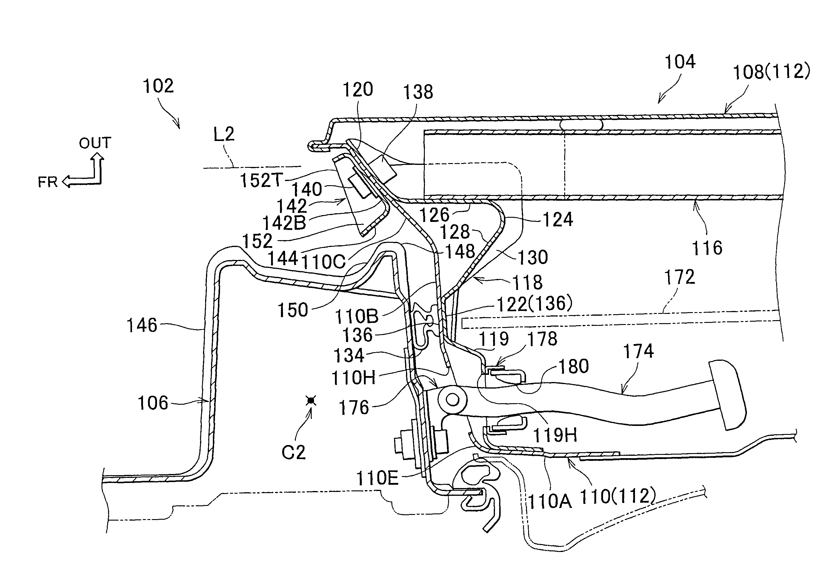
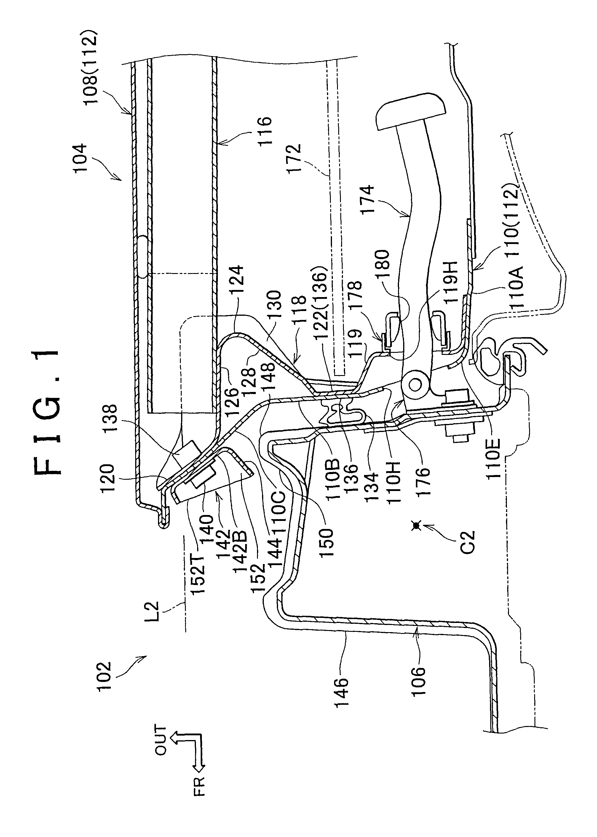
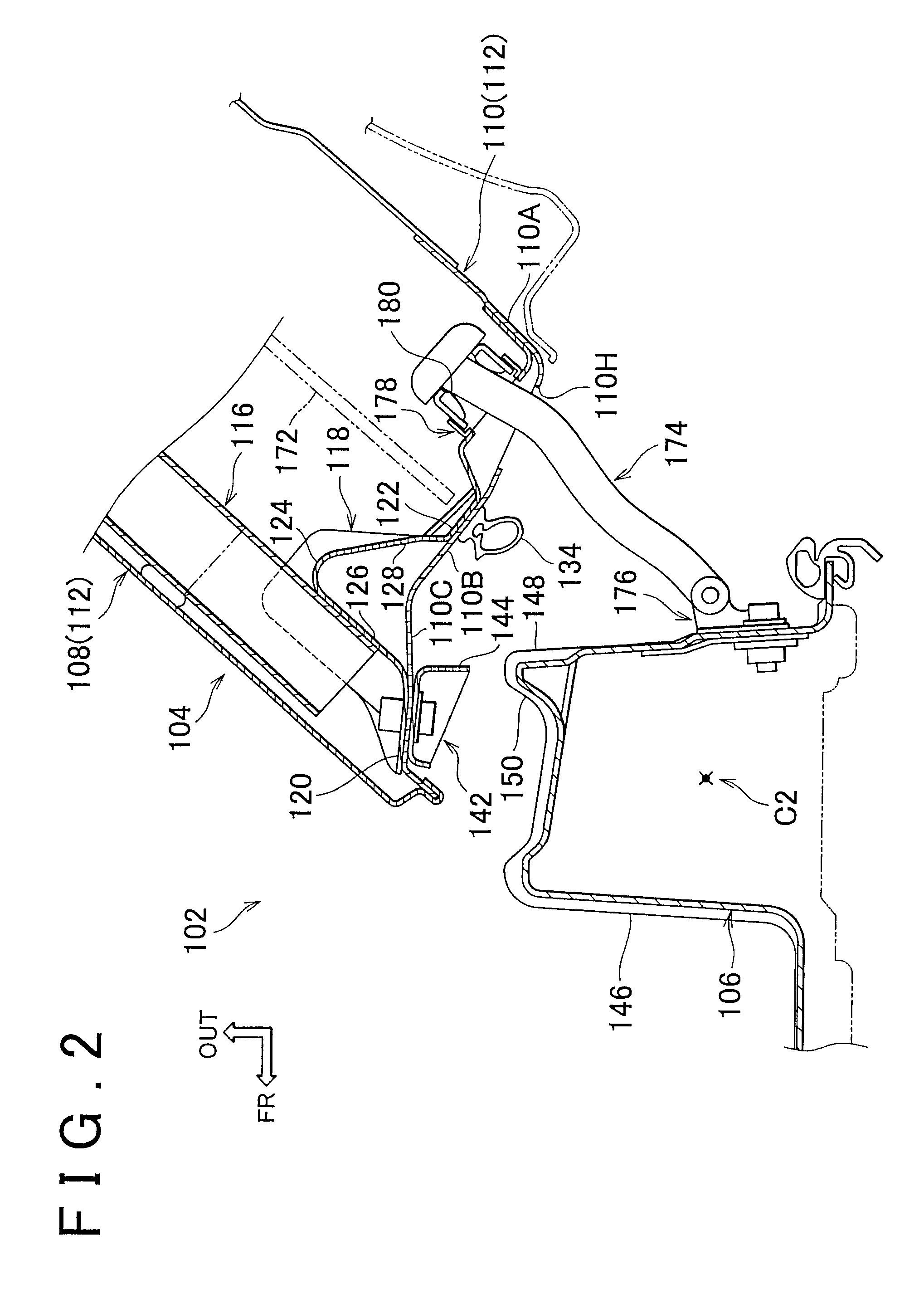
[0039]FIG. 1 shows a partial view of a vehicle body side structure 102 according to the present invention. The vehicle body side structure 102 of this embodiment is applied to a supporting end side of a door 104 supported at one end swingably with respect to the vehicle body, and a body pillar 106 forming a part of the vehicle body at this support end side. FIG. 2 shows the vehicle body side structure 102 in the condition in which the door 104 is swung open. In the following, the forward direction of the vehicle is indicated by the arrow FR, the upward direction by the arrow UP, and the outside in the vehicle widthwise direction by the arrow OUT.

[0040]As can be understood from FIG. 1 and FIG. 2, the door 104 has a door inner panel 110 and a door outer panel 108. The door outer panel 108 has a substantially flat plate shape, and the door inner panel 110 is formed by a flat-plate part 110A positioned inside the door outer panel 108 in the vehicle widthwise direction and substantially ...

fourth embodiment

[0075]In the fourth embodiment configured in this manner, because the fixed part 416 of the impact beam 414 is disposed along the load transmission part 128, the load transmission part 128 is reinforced. Also, by eliminating the joining part 120, it is possible to reduce the size and the weight of the impact beam extension 418.

[0076]FIG. 11 shows an impact beam extension 508 of the fifth embodiment of the present invention. In the fifth embodiment, because only the shape of the impact beam extension 508 differs from the first embodiment, and all other elements are the same, only the difference is described below.

fifth embodiment

[0077]The impact beam extension 508 of the fifth embodiment further includes the lower hinge retainer 510 and they are integrally formed. With the lower hinge retainer 510, a load at the time of a side impact is transmitted not only to the impact beam extension 508, but also the hinge retainer 510 and further to the hinge, resulting in distribution of the load.

[0078]FIG. 12 shows an impact beam extension 606 of the sixth embodiment of the present invention. In the sixth embodiment, because only the shape of the impact beam extension 606 differs from the first embodiment, and all other elements are the same, only the difference is described below.


PUM


Abstract

In a vehicle body side structure, an impact beam (116) is mounted to a door inner panel (110) by an impact beam extension (118). A part of the impact beam extension (118) that extends from an impact beam fixing part (126) to the door inner panel (110) serves as a load transmission part (128) capable of transmitting a load from the impact beam (116) to the door inner panel (110), and the extension line therefrom is directed at the centroid C2 of the body pillar (106). With a simple structure such as this, at the time of a side impact it is possible to transfer a load from the impact beam (116) in a straight line to the centroid C21 of the body pillar (106) while suppressing the twisting moment of the body pillar (106).

Description

CROSS-REFERENCE TO RELATED APPLICATIONS[0001]This application is a national phase application of International Application No. PCT / IB2007 / 000485, filed Mar. 1, 2007, and claims the priority of Japanese Application No. 2006-058419, filed Mar. 3, 2006, the contents of both of which are incorporated herein by reference.BACKGROUND OF THE INVENTION[0002]1. Field of the Invention[0003]The present invention relates to a vehicle body side structure.[0004]2. Description of the Related Art[0005]The side structure of a vehicle body, and particularly in the door structure thereof, for example as described in Japanese Patent 3443620, has an impact beam mounting structure in which the front edge and the rear edge of an impact beam are mounted to a door inner panel by an extension member.[0006]In an actual vehicle body side structure, it is desirable that the load applied to the impact beam from outside, in the vehicle width direction, be reliably transmitted to the pillar. The additional provisio...

Claims


Application Information

Patent Timeline
Patent Type & Authority Patents(United States)
IPC IPC(8): B62D21/15B60J5/04
CPCB60J5/0437B60J5/0443E05C17/203E05B77/02
Inventor ENDO, YOSHIHIDEMAKINO, KOJIINAMORI, SHIGERU
Owner TOYOTA JIDOSHA KK
Why Eureka
Try Eureka