Adjustable holding system

a technology of holding system and adjustment mechanism, which is applied in the direction of drilling/boring measurement device, portability drilling machine, manufacturing tools, etc., can solve the problems of loss of previously set hole spacing, difficulty in operation, and lack of locking mechanism, so as to reduce cleanup time and keep the work area clean during operation

Active Publication Date: 2012-07-31
KREG ENTERPRISES
View PDF77 Cites 24 Cited by
  • Summary
  • Abstract
  • Description
  • Claims
  • Application Information

AI Technical Summary

Benefits of technology

[0017]In one embodiment, the use of a rear actuated clamp assembly with the fixed base allows users, for the first time, to conveniently clamp a workpiece into place without the need to reach around in front of the workpiece. This feature is particularly useful for larger workpieces. In another embodiment, the additional or alternative use of a dust catcher together with the fixed base keeps the work area clean during operation and reduces cleanup time. In yet another embodiment, a user is able to, for the first time, secure a portable base to a work surface.
[0018]Various embodiments of the adjustable holding systems or jigs of the present invention also allow a user, for the first time, to drill pocket holes in materials of various thicknesses using a guide assembly capable of providing essentially vertical adjustability without the need for separate components and further being interchangeable between different bases, such as a portable base and a fixed base. The unique design of various embodiments of the guide assembly and base (i.e., portable base and / or substantially vertical portion of the fixed base) result in a co-planar relationship of the vertical surfaces of both components when the guide assembly is inserted therein, which provides a substantially smooth surface to support a workpiece in one or more drilling environments. In one embodiment, these novel features are combined with a guide assembly having fixed spacing between guide channels, such as fixed varied spacing. Use of fixed spacing eliminates the need to adjust the holding device or workpiece between drilling to obtain the desired spacing between pocket holes.

Problems solved by technology

Others which seek to provide infinite height adjustment do not provide any type of locking mechanism to secure the drill guide into position without a clamp.
Such designs, however, can be difficult to operate properly, particularly when larger workpieces need to be drilled.
Many devices on the market today attempt to provide drill guides which can be moved for use in different applications although proper spacing is typically not maintained.
For example, conventional guides intended for use with a fixed base are often provided on a rod along which they are free to move when not secured to the fixed base, resulting in loss of previously set hole spacing, thus requiring realignment of the guides with respect to each other.
This is not only time-consuming but can lead to inaccurate results.

Method used


Image

  • Adjustable holding system
  • Adjustable holding system
  • Adjustable holding system

Examples


Embodiment Construction

[0050]In the following detailed description of the preferred embodiments, reference is made to the accompanying drawings which form a part hereof, and in which is shown by way of illustration specific preferred embodiments in which the invention may be practiced. These embodiments are described in sufficient detail to enable those skilled in the art to practice the invention, and it is to be understood that other embodiments may be utilized and that mechanical, procedural, and other changes may be made without departing from the spirit and scope of the present inventions. The following detailed description is, therefore, not to be taken in a limiting sense, and the scope of the present invention is defined only by the appended claims, along with the full scope of equivalents to which such claims are entitled.

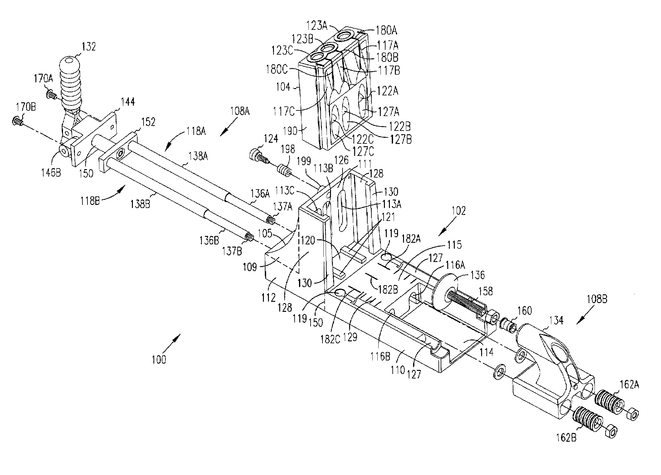
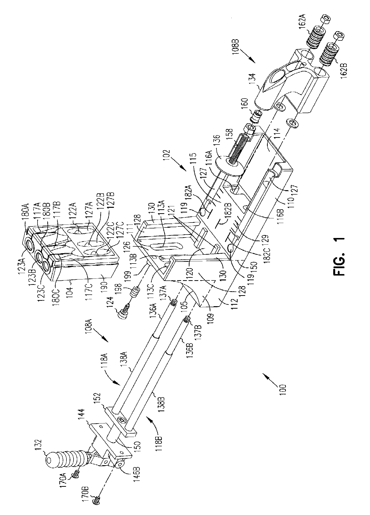
[0051]An adjustable holding system is disclosed. In one embodiment, the adjustable holding system comprises a fixed base or a portable base and a guide assembly which cooperate ...


PUM

PropertyMeasurementUnit
lengthaaaaaaaaaa
lengthaaaaaaaaaa
lengthaaaaaaaaaa

Abstract

Adjustable holding systems, as well as methods of using, may include a fixed base adapted for use on a work surface, the fixed base having a rear actuated clamp assembly secured thereto. Other systems and methods may include one or more bases adapted for use on a work surface; and a guide assembly removably securable to the one or more bases, wherein the guide assembly provides infinite vertical adjustability which can be retained without clamping. Yet other systems and methods may include a portable base securable to a work surface, the portable base having a portable base opening.

Description

CROSS-REFERENCE TO RELATED APPLICATION[0001]This application is a continuation of application Ser. No. 11 / 104,276, filed Apr. 12, 2005 now U.S. Pat. No. 7,641,425, entitled “Adjustable Holding Systems And Methods Of Using Same,” which is incorporated herein by reference.FIELD OF THE INVENTION[0002]This invention relates generally to holding systems and, more particularly, to adjustable holding systems and methods of using same.BACKGROUND OF THE INVENTION[0003]Pocket hole wood joinery involves joining boards by inserting a fastener at an angle through the edge of one board into the other. Such joints are commonly used for face frames, cabinet boxes, leg-to-rail joinery in chairs and tables, and so forth. Drill guides or jigs are used to drill the holes through which the fasteners or pocket screws are inserted into the adjoining workpiece.[0004]Typical jigs or pocket hole devices provide for drilling of specifically sized workpieces with minimal ability to adjust the drill guide heigh...

Claims


Application Information

Patent Timeline
Patent Type & Authority Patents(United States)
IPC IPC(8): B23B47/28
CPCB23B47/287B23B49/005B23B2247/10B23B2247/12Y10T408/50B23B2260/088Y10T408/563Y10T408/567B23B2260/0485
Inventor SOMMERFELD, CRAIG ACLARK, SCOTT L
Owner KREG ENTERPRISES
Why Eureka
Try Eureka