Ballast circuit for a gas-discharge lamp having a filament drive circuit with monostable control

Inactive Publication Date: 2012-07-31
UNIVERSAL LIGHTING TECHNOLOGIES
View PDF12 Cites 0 Cited by
  • Summary
  • Abstract
  • Description
  • Claims
  • Application Information

AI Technical Summary

Benefits of technology

[0010]This invention is directed to a ballast circuit that utilizes a filament drive circuit to control the heating effect of the pulsed heating signal on the filaments of a gas-discharge lamp. The ballast circuit does not require expensive electronic components and is capable of controlling the heating effect of the pulsed heating signal without a parallel resonant tank or complicated digital counting schemes.
[0013]The set terminal of the SR flip-flop receives a clock signal from the inverter. A timing pulse of the clock signal triggers the logic device to close the switch device and begin the transmission of a pulse. The reset terminal of the SR flip-flop is coupled to the output of a comparator that senses a voltage level across a resistor in series with the switch device. The voltage across the resistor in series with the switch device is proportional to the current through the primary winding. The voltage, against which the comparator compares the voltage across the resistor in series with the switch device, is preset so as to control the peak instantaneous current flowing through the primary winding, which will control the cycle by cycle energy transferred to the lamp filaments. When the voltage across the resistor in series with the switch device is at or above a threshold level, the comparator transmits an output signal to the reset terminal that causes the SR flip-flop to open the switch device and end the pulse. The filament drive circuit can adjust the threshold level and control the pulse width of the pulses on the pulsed heating signal. In this manner, the heating effect of the pulsed heating signal may be controlled without a parallel resonant circuit or complicated digital counting schemes.

Problems solved by technology

The problem with prior art filament drive circuits is that they either interfere with the operation of the inverter or they require a complicated coordination scheme with the clock signals to adjust the heating effect of the pulsed heating signal.
Unfortunately, this also has the effect of adjusting the resonant frequency of the inverter's resonant circuit.
Complicated and expensive circuitry is required to achieve the desired heating effect while maintaining the desired dimming level of the lamp.
Unfortunately, these circuits require a processor to determine the number of clock cycles associated with a desired pulse width for the pulsed heating signal and to count clock cycles during the generation of a pulse.
A processor then implements a complicated digital counting scheme to time the start and end of the pulses which reduces the reliability of the circuit and increases its cost.

Method used


Image

  • Ballast circuit for a gas-discharge lamp having a filament drive circuit with monostable control
  • Ballast circuit for a gas-discharge lamp having a filament drive circuit with monostable control
  • Ballast circuit for a gas-discharge lamp having a filament drive circuit with monostable control

Examples


Embodiment Construction

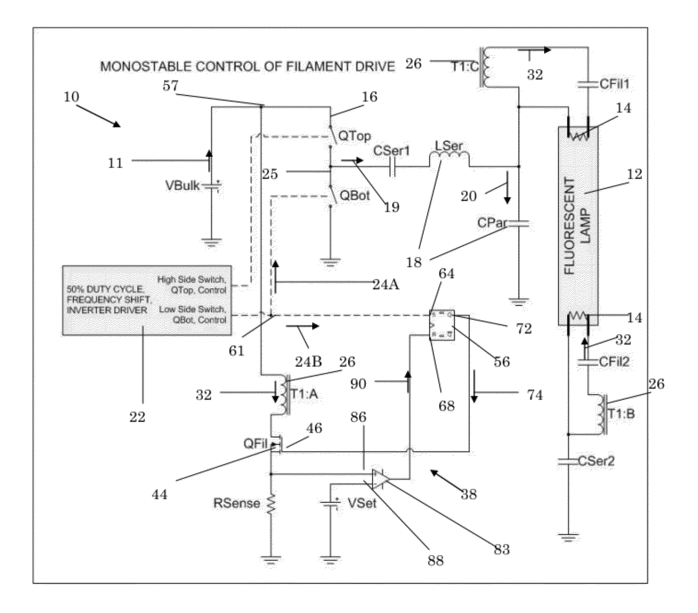
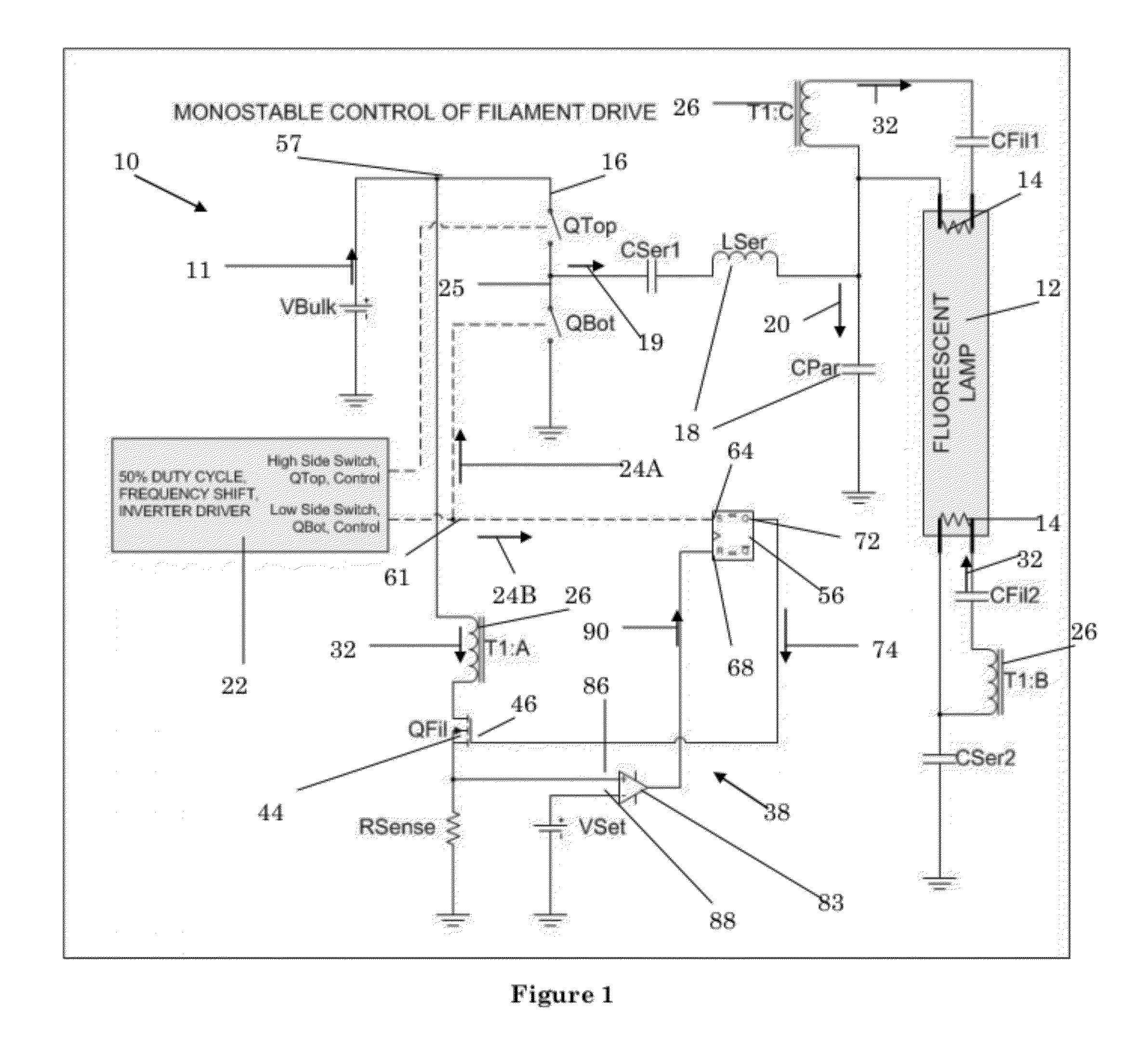
[0018]Referring now to FIG. 1, an embodiment of a ballast circuit 10 for powering a gas-discharge lamp 12 in accordance with the invention is shown. The ballast circuit 10 has an inverter 16 that receives a DC voltage 11 from a DC voltage source, V_Bulk. The DC voltage source, V_Bulk, may be an independent DC source such as a battery or the like, an AC to DC converter (not shown) in ballast circuit 10 that converts an AC line signal from a power line into the DC voltage 11, or any other type of power source that generates a DC signal.

[0019]As is known in the art, inverter 16 utilizes inverter switch devices, QTop, QBot to generate a periodic signal 19 from the DC voltage 11. DC blocking capacitor, C_Ser1, blocks the DC components of the periodic signal 19. Resonant circuit 18 filters the periodic signal 19 to provide an AC voltage 20 at the appropriate frequency for powering the gas discharge lamp 12. In this particular embodiment, the resonant circuit 18 is a series resonant circui...


PUM


Abstract

An electronic ballast circuit includes a filament drive circuit that can adjust the pulse width of a pulsed heating signal in accordance with the lamp current to a gas-discharge lamp. A logic device, such as an SR flip-flop, is used to control a switch that is coupled to the primary winding of a filament drive transformer coupled to the lamp filaments. The logic device opens and closes the switch device to generate the pulses of the pulsed heating signal and thus controls the pulse width of the pulses. A clock signal triggers logic device to start a pulse while the end of the pulse is determined by a signal level across a resistor in series with the primary winding of filament drive transformer. Once this signal level is at or above a threshold level, logic device switches the switch device to end the pulse.

Description

CROSS-REFERENCES TO RELATED APPLICATIONS[0001]This application claims benefit of the following provisional patent application which is hereby incorporated by reference: U.S. Patent Application No. 61 / 157,837, filed Mar. 5, 2009.[0002]A portion of the disclosure of this patent document contains material that is subject to copyright protection. The copyright owner has no objection to the reproduction of the patent document or the patent disclosure, as it appears in the U.S. Patent and Trademark Office patent file or records, but otherwise reserves all copyright rights whatsoever.STATEMENT REGARDING FEDERALLY SPONSORED RESEARCH OR DEVELOPMENT[0003]Not ApplicableREFERENCE TO SEQUENCE LISTING OR COMPUTER PROGRAM LISTING APPENDIX[0004]Not ApplicableBACKGROUND OF THE INVENTION[0005]Electronic ballast circuits use filament drive circuits to provide a heating voltage to the filaments of a gas-discharge lamp and to ensure that the filaments are properly heated during the operation of the lamp...

Claims


Application Information

Patent Timeline
IPC IPC(8): H01J13/46
CPCH05B41/295
Inventor MAYS, STEVE
Owner UNIVERSAL LIGHTING TECHNOLOGIES
Why Eureka
Try Eureka