Combined chain ring protector and chain guide

a technology of chain ring protector and guide, which is applied in the direction of bicycle safety arrangement, gear, bicycle crank, etc., can solve the problems of chain ring, chain ring, chain ring and forward portion of the bicycle drivetrain, chain shake violently, chain ring and other problems, to achieve the effect of strengthening the structural integrity of the guard

Active Publication Date: 2012-08-07
EKO SPORT INC
View PDF26 Cites 43 Cited by
  • Summary
  • Abstract
  • Description
  • Claims
  • Application Information

AI Technical Summary

Benefits of technology

[0011]A mounting bracket is preferably affixed to the bottom bracket shell of the bicycle. An upper chain guide is affixed to an upper extension of the bracket, and the upper guide preferably contains the chain on three sides of the chain: inner, outer and upper. A lower guide retains the chain on an idler pulley, forms a barrier against derailment during backpedaling and is attached to the mounting bracket. A guard with a portion extends downwardly from the mounting bracket past the chain ring and a relatively straight portion of the guard extends rearwardly along the lower chainline. The rearward bracket extension that provides the point of attachment for the lower guide also reinforces the structural integrity of the guard.

Problems solved by technology

The forward portion of the bicycle drivetrain, consisting of the bottom bracket bearings, crank, chain ring, and chain is vulnerable to damage from underside impacts with rocks, stumps and other road and trail obstacles.
The same rough terrain that presents underside obstacles capable of damaging the drivetrain can, when struck by the bicycle's wheels, jar the entire bicycle, thereby causing the chain to shake violently enough to derail it from the chain ring.
A derailed chain can result in damage to mechanical components as well as inconvenience and even physical danger to the rider.

Method used


Image

  • Combined chain ring protector and chain guide
  • Combined chain ring protector and chain guide
  • Combined chain ring protector and chain guide

Examples


Embodiment Construction

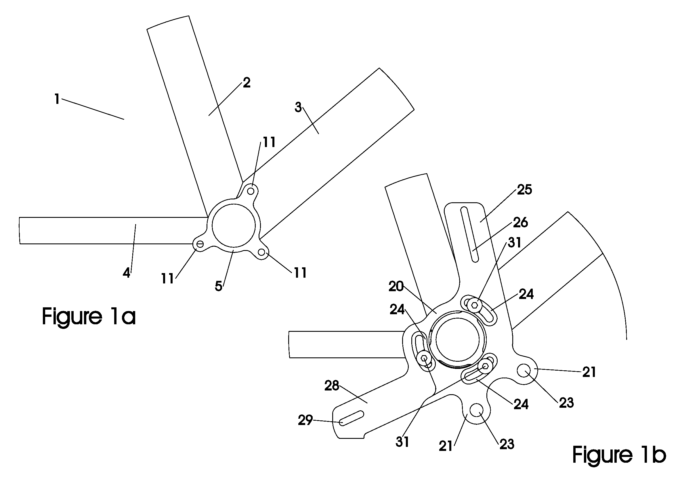
[0021]FIG. 1a shows a portion of a conventional bicycle frame 1 consisting of the seat tube 2, the downtube 3, and the right chainstay 4. The tubes join at the bottom bracket shell 5, which contains radial tabs, such as the bosses 11, for attachment of a chain guide, and through which a conventional crank rotatably extends. The terms “bottom bracket shell” and “lower bracket sleeve” are interchangeable.

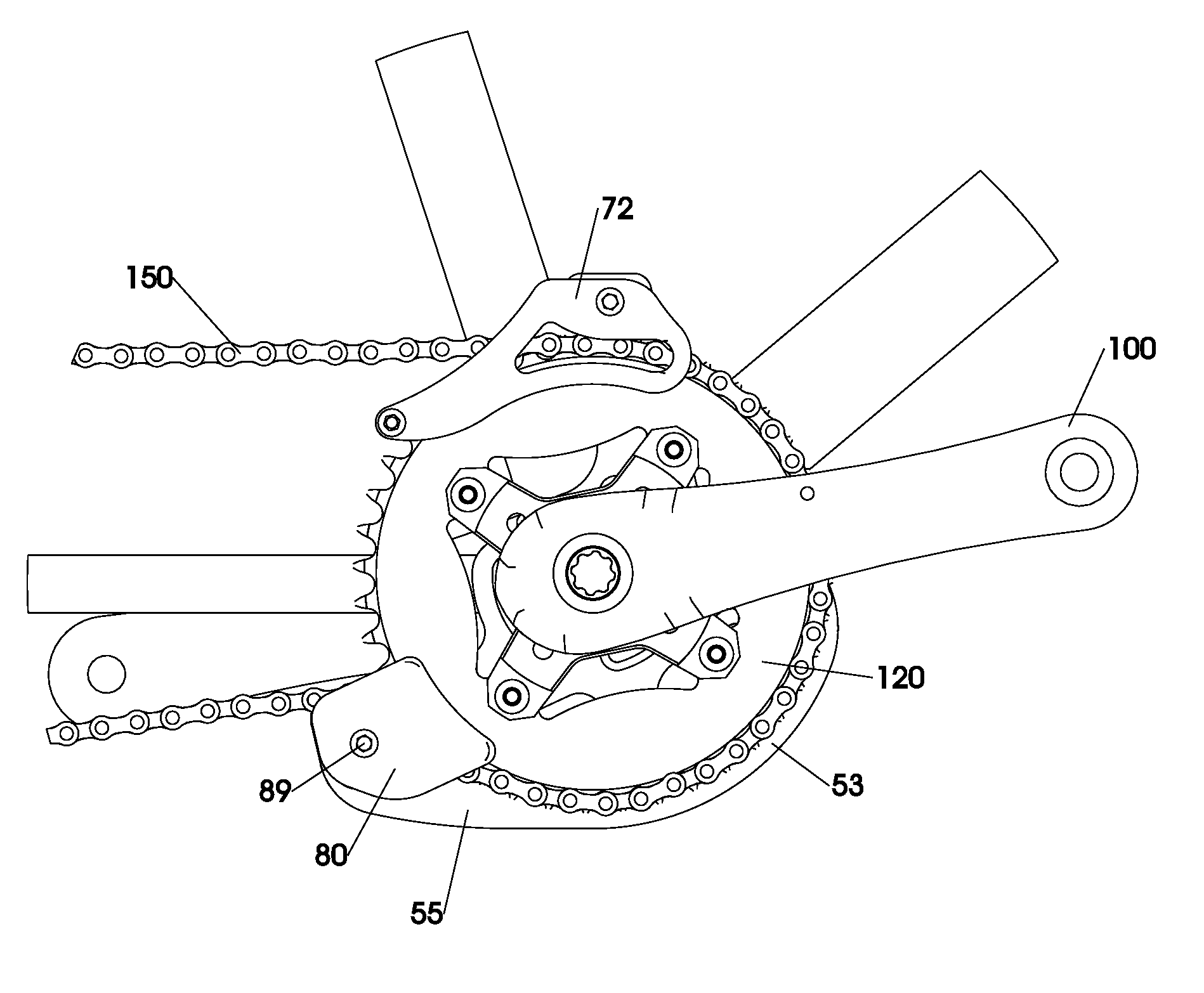
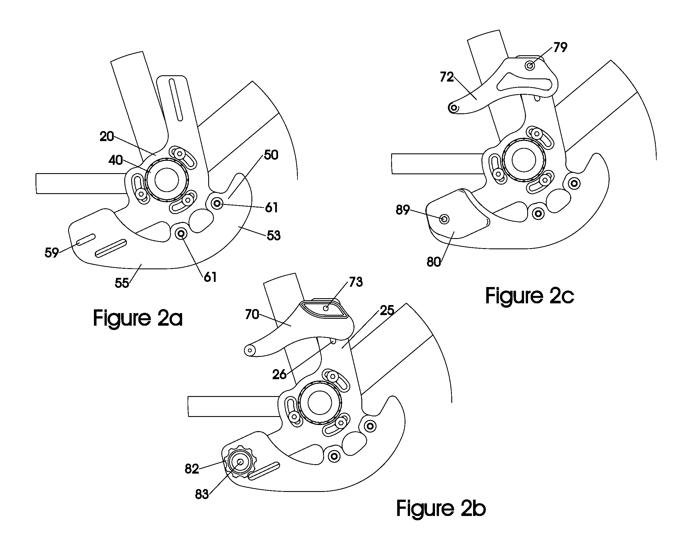
[0022]Referring to FIG. 1b, the preferred embodiment of the mounting bracket 20 of the present invention is shown mounted in its operable position to the bottom bracket shell 5 by the screws 31 inserted through the arcuate slots 24 formed at spaced locations on the bracket 20, preferably aligned at International Standard Chain Guide (ISCG) mounting locations, for mounting to the bosses 11 on the bottom bracket shell 5 at ISCG positions. Although it is preferred for the slots 24 to be formed at ISCG locations, it should be noted that there may be other standards, including but not limi...


PUM


Abstract

A combined chain guide and chain ring protector for a bicycle for off-road use having a lower bracket sleeve, a chain ring around which a drive chain extends and a chain ring outer radius. The protector includes a mounting bracket secured at the lower bracket sleeve and a guard mounted thereto. An outer edge of the guard extends beyond the outer radius of the chain ring, thereby protecting a portion of the chain ring from inadvertent impacts. The chain guide extends from the mounting bracket along a path of the drive chain, and preferably includes an upper guide having an inner barrier positioned inboard of the bicycle chain an outer barrier positioned outboard of the inner barrier and an upper barrier positioned above the bicycle chain for preventing the chain from derailing from the chain ring in an upward direction.

Description

CROSS-REFERENCES TO RELATED APPLICATIONS[0001]This application claims the benefit of U.S. Provisional Application No. 60 / 968,723 filed Aug. 29, 2007.STATEMENT REGARDING FEDERALLY-SPONSORED RESEARCH AND DEVELOPMENT[0002](Not Applicable)REFERENCE TO AN APPENDIX[0003](Not Applicable)BACKGROUND OF THE INVENTION[0004]1. Field of the Invention[0005]This invention relates generally to devices for preventing damage to the chain ring, chain, crank and bottom bracket of a bicycle and devices that maintain the chain safely on the teeth of the chain ring. Specifically, the invention improves upon the prior art by uniquely integrating a chain guide with an improved chain ring protector.[0006]2. Description of the Related Art[0007]The forward portion of the bicycle drivetrain, consisting of the bottom bracket bearings, crank, chain ring, and chain is vulnerable to damage from underside impacts with rocks, stumps and other road and trail obstacles. The need to protect this part of the bicycle from...

Claims


Application Information

Patent Timeline
Patent Type & Authority Patents(United States)
IPC IPC(8): B62J13/00B62M9/12
CPCB62J13/00B62M2009/007
Inventor CRANSTON, RYAN K.ROGERS, JAMES K.
Owner EKO SPORT INC
Why Eureka
Try Eureka