High-pressure vessel for growing group III nitride crystals and method of growing group III nitride crystals using high-pressure vessel and group III nitride crystal

a technology of nitride crystals and high-pressure vessels, which is applied in the direction of crystal growth process, polycrystalline material growth, transportation and packaging, etc., can solve the problems of difficult to grow gan crystal ingots, disadvantages in expanding the reactor scale, and affecting the realization of high-end optical and electronic devices, so as to reduce the parasitic deposition of polycrystalline gan, improve structural quality, and improve the effect of structure quality

Active Publication Date: 2012-08-07
SIXPOINT MATERIALS
View PDF87 Cites 20 Cited by
  • Summary
  • Abstract
  • Description
  • Claims
  • Application Information

AI Technical Summary

Benefits of technology

[0021]In addition, the current invention discloses a method of reducing parasitic deposition of polycrystalline GaN on the inner surface of the pressure vessel while optionally improving structural quality and without reducing growth rate. Because of the retrograde solubility of GaN in the ammonothermal growth using basic mineralizers, the temperature in the crystallization region is conventionally set higher than the temperature in the nutrient region. We, however, discovered that GaN can be grown by setting the temperature of the crystallization region slightly lower than the temperature of the nutrient region. By utilizing this “reverse” temperature setting for growth, parasitic deposition of GaN on the reactor wall was greatly reduced. Moreover, the structural quality of grown crystal was improved without sacrificing growth rate.

Problems solved by technology

However, the majority of these devices are grown epitaxially on heterogeneous substrates, such as sapphire and silicon carbide since GaN wafers are extremely expensive compared to these heteroepitaxial substrates.
The heteroepitaxial growth of group III-nitride causes highly defected or even cracked films, which hinders the realization of high-end optical and electronic devices, such as high-brightness LEDs for general lighting or high-power microwave transistors.
However, due to the high melting point and high nitrogen vapor pressure at elevated temperature, it has been difficult to grow GaN crystal ingots.
The latter two methods have disadvantages in expanding the reactor scale.
For the ammonoacidic approach, it is extremely expensive to use a Pt-liner in a large-scaled pressure vessel.
As for the internal capsule, it is structurally very challenging to operate the capsule reactor larger than 2″ diameter.
Because of this difference, it is not straightforward to apply the solvothermal method to grow group III nitride crystals and more improvements are required to realize mass production of GaN wafers by the ammonothermal method.
First, state-of-the-art ammonothermal method [6-10] lacks scalability into industrial production because it is quite difficult to obtain large enough superalloy material to construct a high-pressure vessel.
However, if the solid dimension of the piece being worked (such as its thickness) becomes too large, the grain structure necessary for high-tensile strength cannot be obtained by forging.
This is because the forging pressure is always applied from the surface during the forging process and the grain size at the inner portion of the material tends to be unaffected if the work size exceeds a certain size.
Cracking during the forging / cooling process is also profound for large diameter rods.
These problems limit the available size of Ni—Cr based precipitation hardenable superalloys.
Another obstacle to apply the ammonothermal method to commercial production of GaN single crystals is mediocre quality of grown crystals.
Currently, their purity, transparency and structural quality are not sufficient for commercial use.

Method used


Image

  • High-pressure vessel for growing group III nitride crystals and method of growing group III nitride crystals using high-pressure vessel and group III nitride crystal
  • High-pressure vessel for growing group III nitride crystals and method of growing group III nitride crystals using high-pressure vessel and group III nitride crystal
  • High-pressure vessel for growing group III nitride crystals and method of growing group III nitride crystals using high-pressure vessel and group III nitride crystal

Examples


example 1

[0077]To solve the above-mentioned problem, a few methods to obtain larger clamps were sought and we discovered it possible to manufacture a large diameter disk with e.g. precipitation hardenable Ni—Cr based superalloy or other metal or alloy by forging as-cast billet along longitudinal direction. With this method, a 17-inch as-cast billet is forged along the longitudinal direction to form a 20-inch diameter, 1-foot thick disk. The forging process usually creates a directional microstructure (grain flow) which determines tensile strength of the material.

[0078]The grain flow of the round rod to construct the body and lids is typically along the longitudinal direction whereas the grain flow of the disks to construct the clamps is along the radial direction. While one might expect a disk with radial grain flow rather than axial grain flow to not have sufficient tensile strength to reliably clamp a lid to a reactor body during use, this difference does not have a significant impact on t...

example 2

[0085]Another method to realize a large diameter high-pressure vessel is to use high-strength steel for the clamp material. Although the maximum practical temperature for high-strength steel (such as 4140) is 550° C., the maximum available size is large enough to fabricate clamps for high-pressure vessel having 12-inch outer diameter. In this case extra caution is necessary to control the clamp temperature. An end region in the reactor that has one or more baffles to impede ammonia flow permits ammonia to cool in an end region, reducing the reactor temperature in that region and allowing a clamp to be formed of a material such as high strength steel that might not otherwise be used to form a clamp. Also, appropriate anti-corrosion coating is advisable in case of ammonia leak since steel is susceptible to corrosion by basic ammonia.

example 3

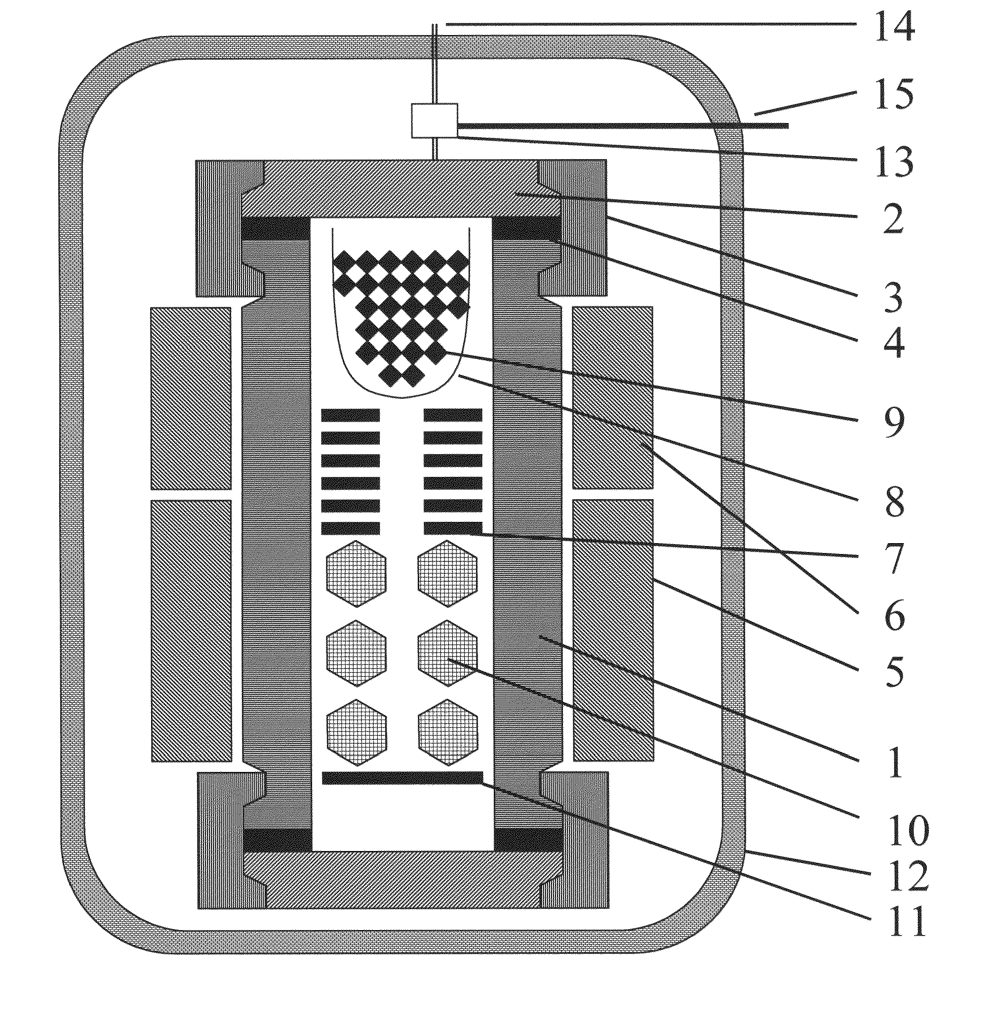
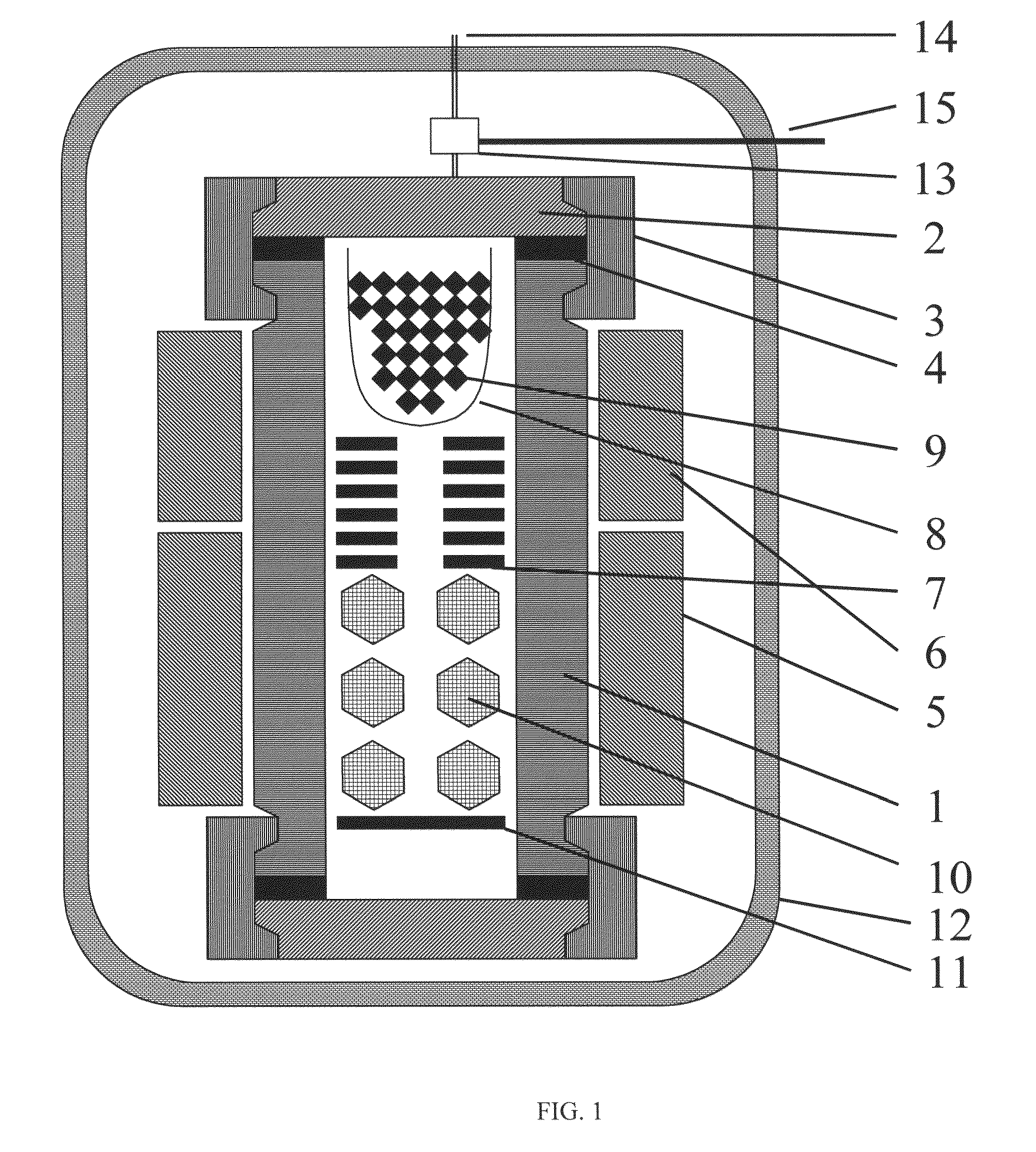
[0086]In this example, a high-pressure vessel having an inner diameter of 1 inch was used to demonstrate the enhanced growth rate by having one or more buffer regions between the crystallization region and the nutrient region. Unlike the Examples 1, 2, this high-pressure vessel has an open end on one side only. The chamber of the high-pressure vessel is divided into several regions. From bottom to top, there were a crystallization region, buffer regions, and a nutrient region. GaN crystals were grown with 2 buffer regions, 5 buffer regions, and 8 buffer regions and the growth rate in each condition was compared. First, the high-pressure vessel was loaded with 4 g of NaNH2, a seed crystal suspended from a flow-restricting baffle having 55 mm-long legs (the first baffle). To create buffer regions, 2 flow restricting baffles with 18 mm legs, 5 flow restricting baffles with 18 mm legs or 8 flow restricting baffles with 10 mm legs were set on top of the first baffle (i.e. buffer regions ...


PUM

PropertyMeasurementUnit
inner diameteraaaaaaaaaa
temperatureaaaaaaaaaa

Abstract

The present invention discloses a high-pressure vessel of large size formed with a limited size of e.g. Ni—Cr based precipitation hardenable superalloy. The vessel may have multiple zones.For instance, the high-pressure vessel may be divided into at least three regions with flow-restricting devices and the crystallization region is set higher temperature than other regions. This structure helps to reliably seal both ends of the high-pressure vessel, and at the same time, may help to greatly reduce unfavorable precipitation of group III nitride at the bottom of the vessel.This invention also discloses novel procedures to grow crystals with improved purity, transparency and structural quality. Alkali metal-containing mineralizers are charged with minimum exposure to oxygen and moisture until the high-pressure vessel is filled with ammonia. Several methods to reduce oxygen contamination during the process steps are presented. Also, back etching of seed crystals and a new temperature ramping scheme to improve structural quality are disclosed.

Description

CROSS REFERENCE TO RELATED APPLICATIONS[0001]The application claims the benefit of priority to U.S. App. Ser. No. 61 / 058,910 entitled “High-Pressure Vessel For Growing Group III Nitride Crystals And Method Of Growing Group Iii Nitride Crystals Using High-Pressure Vessel And Group III Nitride Crystal”, inventors Tadao Hashimoto, Edward Letts, and Masanori Ikari, filed on Jun. 4, 2008, the entire contents of which are incorporated by reference herein as if put forth in full below. The application is also related to PCT application serial number PCT / US2009 / 046317 entitled “High-Pressure Vessel For Growing Group III Nitride Crystals And Method Of Growing Group Iii Nitride Crystals Using High-Pressure Vessel And Group III Nitride Crystal”, inventors Tadao Hashimoto, Edward Letts, and Masanori Ikari, filed on Jun. 4, 2009, the entire contents of which are incorporated by reference herein as if put forth in full below.[0002]This application is also related to the following U.S. patent appl...

Claims


Application Information

Patent Timeline
Patent Type & Authority Patents(United States)
IPC IPC(8): C01B21/06C30B23/00C23C16/00
CPCC30B7/10C30B29/403C30B7/105B32B15/01C30B35/002Y10T428/12028C30B29/406
Inventor HASHIMOTO, TADAOLETTS, EDWARDIKARI, MASANORI
Owner SIXPOINT MATERIALS
Why Eureka
Try Eureka