Wind turbine, aerodynamic assembly for use in a wind turbine, and method for assembling thereof

a technology for aerodynamic assembly and wind turbine, which is applied in the direction of wind turbines with parallel air flow, liquid fuel engine components, wind energy generation, etc., can solve the problems of not providing dynamic control of the torque along the blade, and increasing the angle of attack at the inner portion of the rotor blade, etc., to achieve the effect of increasing the aerodynamic li

Active Publication Date: 2012-08-14
GENERAL ELECTRIC CO
View PDF6 Cites 2 Cited by
  • Summary
  • Abstract
  • Description
  • Claims
  • Application Information

AI Technical Summary

Benefits of technology

[0007]In another aspect, a method of assembling a wind turbine is provided. The wind turbine includes a rotor, a rotatable hub, and a plurality of rotor blades, each of the plurality of rotor blades being attached to the hub. The method includes disposing at least one airfoil body in the rotor, the at least one airfoil body including an aerodynamic profile and an airfoil body root portion, such that the at least one airfoil body is attached to the hub at the airfoil body root portion. The aerodynamic profile is configured for increasing aerodynamic lift of at least an inner portion of a rotor blade.
[0009]By including an airfoil body, which is attached to the hub at the airfoil body root portion, embodiments herein generally facilitate increasing lift of an inner portion of the rotor blades without inevitably requiring a modification of the rotor blades. Furthermore, by facilitating adjustment of the position of the airfoil body relative to the rotor blades, at least some embodiments herein generally facilitate efficiently responding to varying wind conditions.

Problems solved by technology

However, this generally implies a complex blade shape, which may result in a significant cost increase.
Furthermore, this approach for increasing the angle of attack at the inner portion of the rotor blade does not provide dynamic control of the torque along the blade in response to varying wind conditions.
However, such a movable slat may be insufficient or even unsuitable for particular requirements posed by certain wind conditions.

Method used


Image

  • Wind turbine, aerodynamic assembly for use in a wind turbine, and method for assembling thereof
  • Wind turbine, aerodynamic assembly for use in a wind turbine, and method for assembling thereof
  • Wind turbine, aerodynamic assembly for use in a wind turbine, and method for assembling thereof

Examples


Embodiment Construction

[0025]Reference will now be made in detail to the various embodiments, one or more examples of which are illustrated in each figure. Each example is provided by way of explanation and is not meant as a limitation. For example, features illustrated or described as part of one embodiment can be used on or in conjunction with other embodiments to yield yet further embodiments. It is intended that the present disclosure includes such modifications and variations.

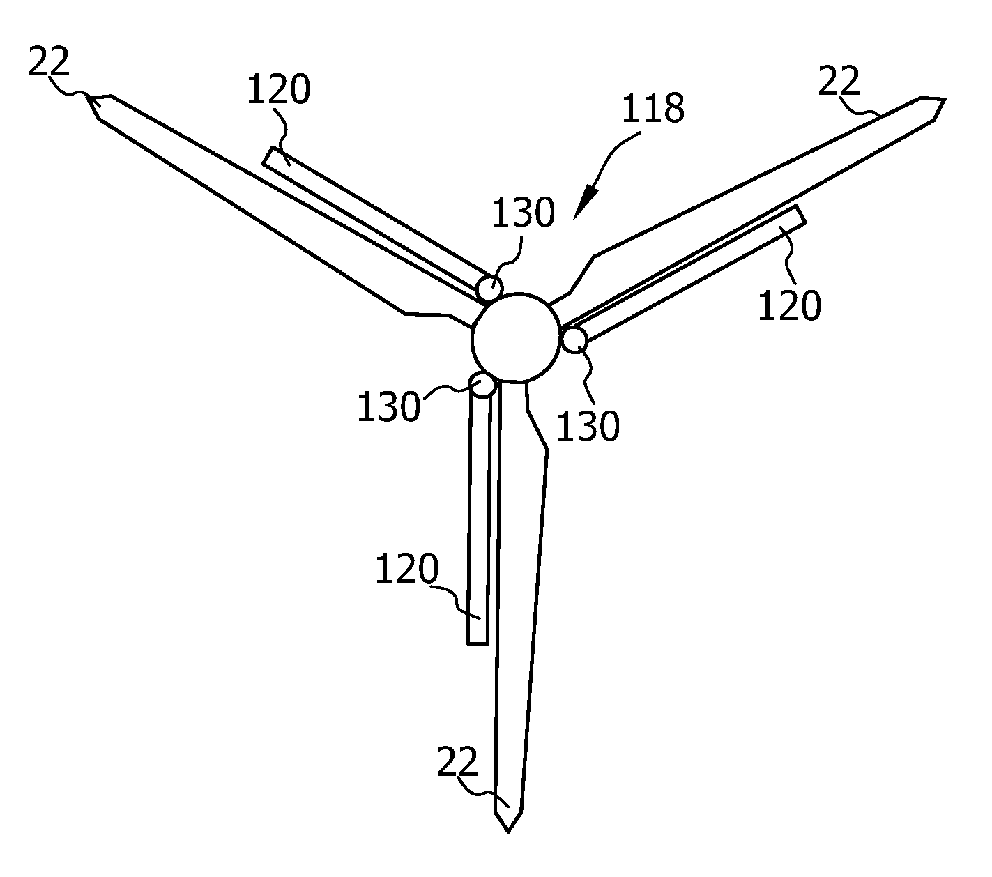
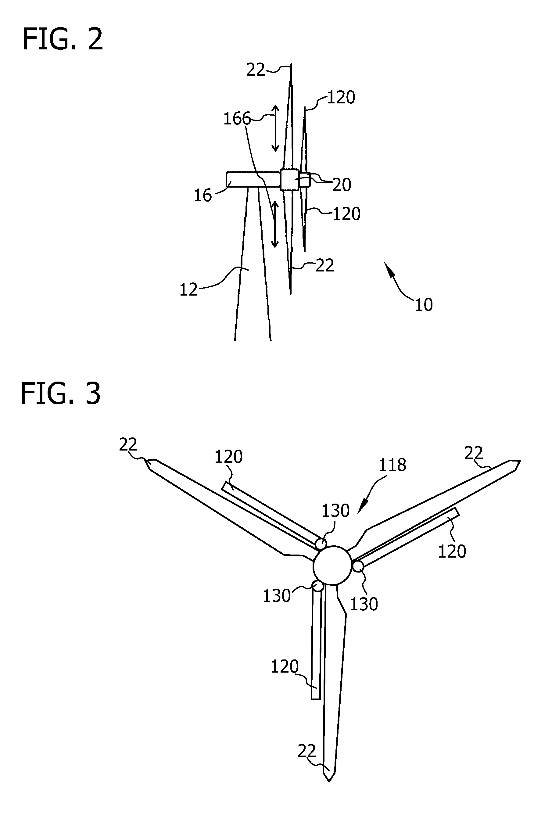
[0026]As set forth above, a wind turbine may include slats coupled to the rotor blades for increasing the torque / lift at an inner portion of the blade (i.e., a portion of the blade proximal to the wind turbine hub or adapted thereto). In particular, a slat is understood as an elongated body having an aerodynamic surface, which is coupled to the leading edge of a rotor blade in a movable manner. Typically, a slat, when deployed, allows the rotor blade to operate at a higher angle of attack at its inner portion. Thereby, lift and ...


PUM

PropertyMeasurementUnit
lengthaaaaaaaaaa
lengthaaaaaaaaaa
lengthaaaaaaaaaa

Abstract

The present disclosure relates to a wind turbine (10) including: a rotor (18) including a rotatable hub (20) and a plurality of rotor blades (22), each of the plurality of rotor blades (22) being attached to the hub (20); and at least one airfoil body (120) including an aerodynamic profile (156) and an airfoil body root portion (122); wherein the aerodynamic profile (156) is configured for increasing aerodynamic lift of at least an inner portion of a rotor blade (22); and the at least one airfoil body (120) is attached to the hub (20) at the airfoil body root portion (122). In addition thereto, the present disclosure relates to an aerodynamic assembly (118) for a wind turbine (10) and a method of assembling a wind turbine (10).

Description

BACKGROUND OF THE INVENTION[0001]The subject matter described herein relates generally to methods and systems for a wind turbine, and more particularly, a method of assembling a wind turbine and an aerodynamic assembly for use with a wind turbine.[0002]Wind turbines generally include a tower and a nacelle mounted on the tower. A rotor is rotatably mounted to the nacelle and is coupled to a generator by a shaft. A plurality of blades extends from the rotor. The blades are oriented such that wind passing over the blades turns the rotor and rotates the shaft, thereby driving the generator to generate electricity. In particular, the wind generates a torque force along the blades. This torque is not constant along the blade. Generally, the torque generated at an inner portion of the blade is smaller than the toque generated at an outer portion of the blade. The torque along the blade generally depends on the particular wind conditions.[0003]The angle of attack (i.e., the angle between th...

Claims


Application Information

Patent Timeline
Patent Type & Authority Patents(United States)
IPC IPC(8): F03D7/00
CPCF03D1/025F03D1/0608F03D7/0232F05B2230/60Y10T29/49316F05B2240/31F05B2260/74Y02E10/721Y02E10/723F05B2240/301Y02E10/72Y02P70/50
Inventor BENITO SANTIAGO, PEDRO LUISYEGRO SEGOVIA, EUGENIO
Owner GENERAL ELECTRIC CO
Why Eureka
Try Eureka