Method for scoring a sheet of brittle material

a brittle material and scoring method technology, applied in glass tempering apparatus, paper/cardboard containers, manufacturing tools, etc., can solve problems such as uncontrollable crack propagation, internal stress in glass, and affected vent propagation

Inactive Publication Date: 2012-08-21
CORNING INC
View PDF12 Cites 56 Cited by
  • Summary
  • Abstract
  • Description
  • Claims
  • Application Information

AI Technical Summary

Benefits of technology

[0007]In one embodiment, a method of scoring a sheet of brittle material is disclosed, comprising forming a flaw in a surface of the sheet of brittle material at an initiation point located a predetermined distance from a first edge of the sheet of brittle material, impinging a beam of electromagnetic radiation on the flaw such that a vent crack is formed at the initiation point, traversing the beam of electromagnetic radiation to propagate the vent crack toward a second edge of the sheet of brittle material, and wherein the vent crack does not intersect the first edge during the traversing, and wherein the beam of electromagnetic radiation is prevented from impinging on the surface of the sheet of brittle material between the initiation point and the first edge by a mask positioned between a source of the electromagnetic radiation and the surface of the sheet of brittle material
[0009]Traversing the laser beam can include propagating the vent crack to a stop point located a predetermined distance from a second edge of the sheet of brittle material such that the vent crack does not propagate to the second edge during the traversing. For example, the beam of electromagnetic radiation can be prevented from impinging on the surface of the sheet of brittle material between the stop point and the second edge by masking the beam of electromagnetic radiation with a suitable mask. However, the vent crack can be prevented from propagating between the stop point and the second edge of the sheet of brittle material by reducing a power of the beam of electromagnetic radiation. To improve scoring further, a jet of coolant on the surface of the sheet of brittle material proximate the traversing beam of electromagnetic radiation that can increase the stress produced in the sheet.
[0011]In another embodiment, a method of scoring a glass sheet is described comprising forming a flaw in a surface of the sheet of glass at an initiation point positioned a predetermined distance from a first edge of the sheet of brittle material, impinging a laser beam on the surface of the sheet of glass at the initiation point to form a vent crack, traversing the laser beam to propagate the vent crack toward a second edge and wherein the laser beam is prevented from impinging on the surface of the sheet of glass between the initiation point and the first edge by a first mask positioned between a source of the laser beam and the surface of the sheet of glass.

Problems solved by technology

However, propagation of the vent can be affected by the background stress in the glass (e.g. internal stress and stress that may be applied to the glass sheet from handling or holding the sheet during the scoring process).
The internal stress in the glass may be caused, for example, by differences in glass thickness produced during the forming process, and consequently by non-uniform glass cooling and a subsequent stress build-up concentrated in the beaded edge area.
If the background stress is high enough, it may cause uncontrolled propagation of the crack, which can start at the sheet edge where the initial flaw is located and deviate away from the desired scoring direction at the moment the laser beam reaches the sheet edge.
More simply put, the thermal stress introduced by the laser beam can initiate a crack that propagates in an undesirable direction.
However, the mask may also be placed in contact with the surface of the sheet of brittle material.

Method used


Image

  • Method for scoring a sheet of brittle material
  • Method for scoring a sheet of brittle material
  • Method for scoring a sheet of brittle material

Examples


Embodiment Construction

[0018]In the following detailed description, for purposes of explanation and not limitation, example embodiments disclosing specific details are set forth to provide a thorough understanding of the present invention. However, it will be apparent to one having ordinary skill in the art, having had the benefit of the present disclosure, that the present invention may be practiced in other embodiments that depart from the specific details disclosed herein. Moreover, descriptions of well-known devices, methods and materials may be omitted so as not to obscure the description of the present invention. Finally, wherever applicable, like reference numerals refer to like elements.

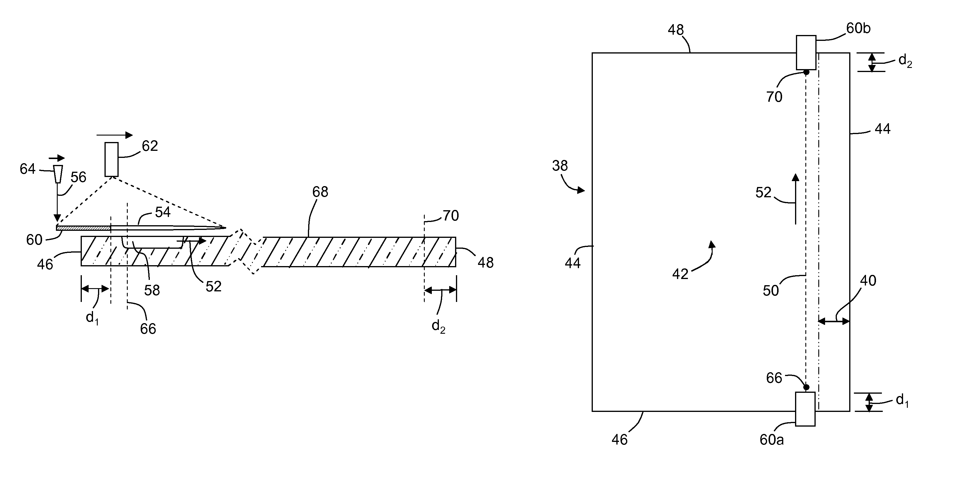
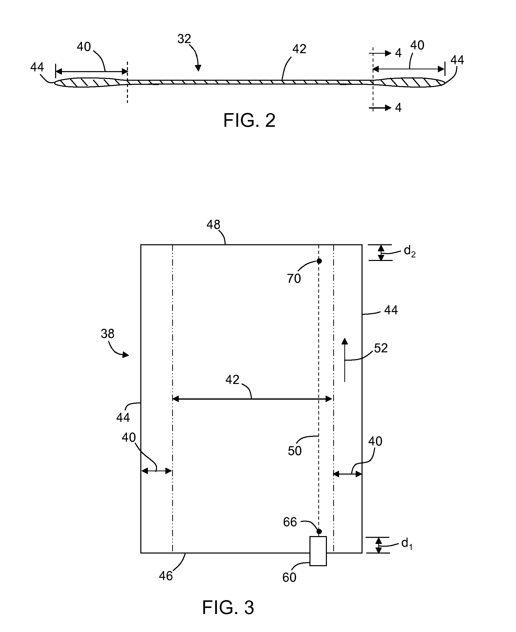
[0019]As used herein, the term “score line” is used to represent a desired or prescribed path for producing a score.

[0020]As used herein, the terms vent or vent crack are used to denote an elongate crack in a brittle material that opens to a surface of the material. The vent may or may not be perpendicular to the s...


PUM

PropertyMeasurementUnit
distanceaaaaaaaaaa
distanceaaaaaaaaaa
distanceaaaaaaaaaa

Abstract

A method of cutting glass that prevents uncontrolled crack propagation when high background stress is present, either in the form of thermal residual stress, external mechanical stress or a combination thereof. The method includes masking an edge of the glass by blocking the beam using highly reflective or absorptive material located near the glass surface, or deposited on the surface in a form of a thin film (or highly reflective paint) to prevent uncontrolled crack initiation and propagation starting from the glass edge. The initiation of the laser scoring is located at a predetermined distance from the glass edge. Yet another aspect of the invention embodies stopping propagation of the vent at the exiting end of the score line.

Description

BACKGROUND OF THE INVENTION[0001]1. Field of the Invention[0002]This invention is directed to a method of scoring a sheet of brittle material, and in particular, a method for scoring a glass sheet that minimizes uncontrolled crack propagation.[0003]2. Technical Background[0004]Mechanical tools are conventionally used for glass scoring. Alternatively, a laser beam, such as a CO2 laser beam at a wavelength of 10.6 μm, may be used. Typically, the glass is rapidly cooled immediately after heating by the laser to create transient tensile stress in the glass via thermal shock.[0005]During laser scoring, a median crack (i.e. partial vent) is created that extends into the body of the glass. To create the vent, a small initial flaw is formed on the glass edge. The initial flaw may then be transformed into the vent and propagated by the laser beam. The initial flaw can be made by different methods. For example, the flaw may be introduced by a laser pulse or by a mechanical tool such as a scri...

Claims


Application Information

Patent Timeline
Patent Type & Authority Patents(United States)
IPC IPC(8): C03B33/09C03B33/00
CPCC03B33/0215C03B33/091C03B33/09Y10T83/0341Y10T83/0333B23K26/364B23K26/0613C03B33/033
Inventor ABRAMOV, ANATOLI ANATOLYEVICHCAVALLARO, III, NICHOLAS DOMINICKEMMERER, MARVIN WILLIAMZHOU, NAIYUE
Owner CORNING INC
Why Eureka
Try Eureka