Reporting system for on-vehicle brake lathe

Active Publication Date: 2012-08-21
BONITA IP
View PDF8 Cites 81 Cited by
  • Summary
  • Abstract
  • Description
  • Claims
  • Application Information

AI Technical Summary

Benefits of technology

[0020]While the above system can be employed on any on-vehicle disk brake lathe, it has been found that on-vehicle disk lathes which are hub-mounted have particular utility and, for such lathes, misalignment between axis of rotation of the brake disk and the axis of rotation of the lathe can result in cutting lateral runout into the turned brake disk. To avoid excessive lateral runout being created, these lathes are provided with alignment mechanisms. Dynamic alignment simplifies the operation of the lathe by providing an automatic correction ro

Problems solved by technology

While such instruments can provide the lathe operator information regarding the current stage of the resurfacing procedure, they do not provide guidance for inexperienced lathe operators, and do not provide records of the machining operations performed by the lathe.
This met

Method used


Image

  • Reporting system for on-vehicle brake lathe
  • Reporting system for on-vehicle brake lathe
  • Reporting system for on-vehicle brake lathe

Examples


Embodiment Construction

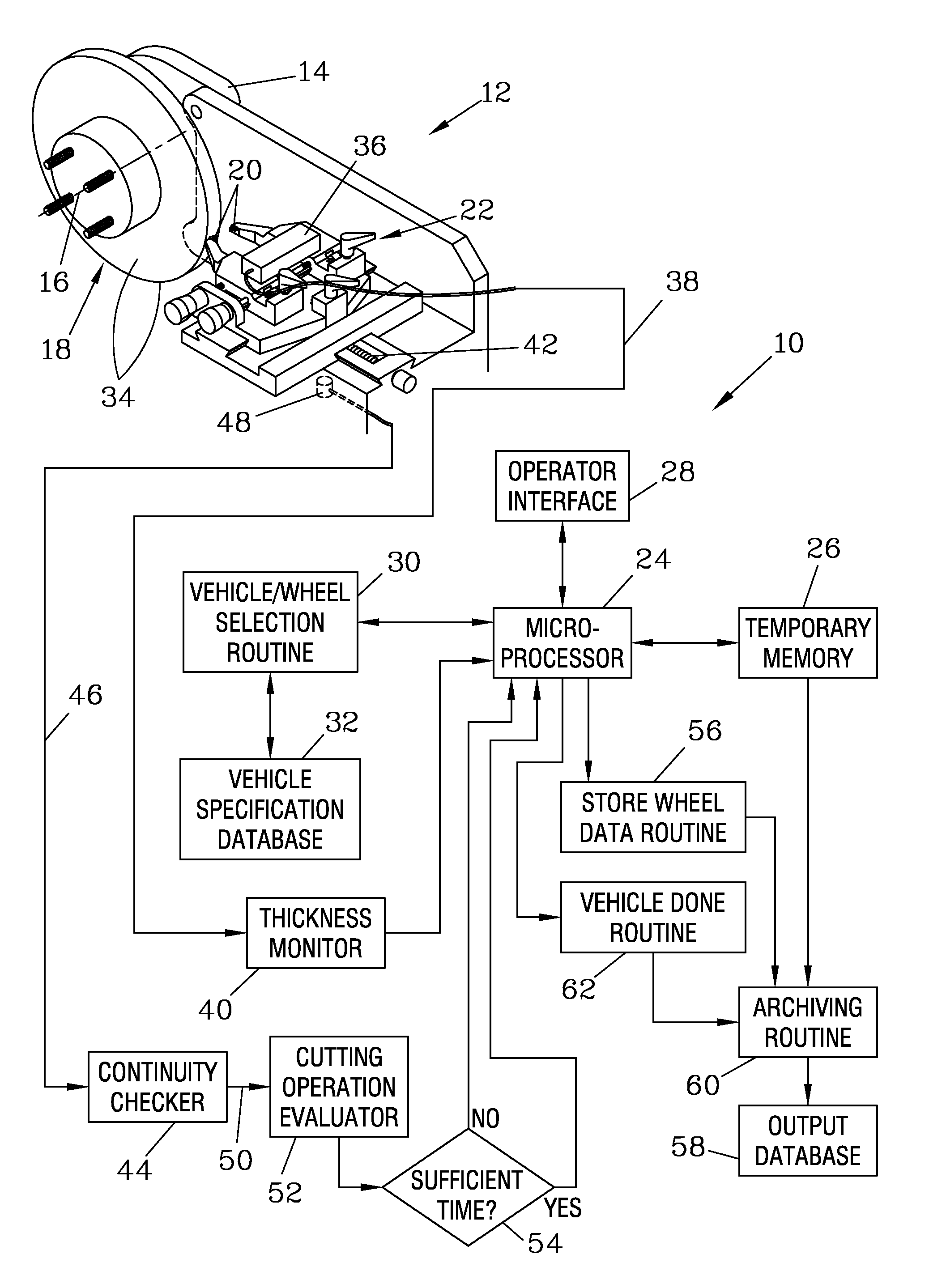
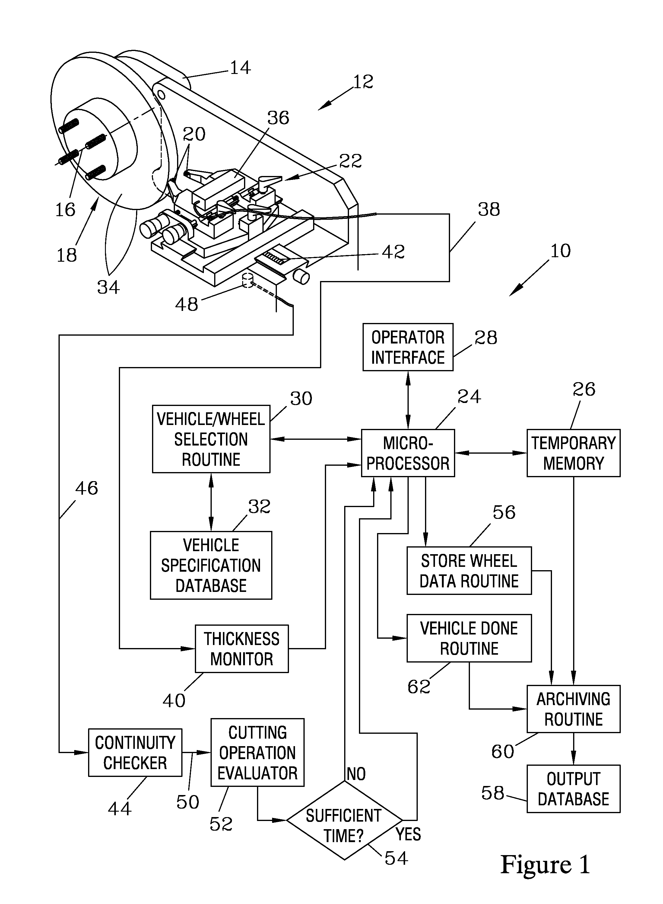
[0038]FIG. 1 is a schematic view of one embodiment of the present invention, a lathe reporting system 10 which operates with a caliper mounted on-vehicle disk brake lathe 12. Since the lathe 12 mounts to a caliper-mounting structure 14 on the vehicle (not shown), rather than to the wheel hub, there is no issue of the alignment of the lathe 12 with respect to a hub axis 16 such as there is when a hub-mounted brake lathe is employed. The caliper mounting structure 14 is affixed with respect to a frame of the vehicle such that the motion of the disk-engaging surfaces of the brake calipers will be parallel to the axis 16 of the disk 18 during service. Thus, the lathe 12 can be designed such that, when the lathe 12 is affixed to this structure 14, the lathe 12 is aligned such that the motion of tool bits 20 of the lathe 12 with respect to the disk 18 is normal to the disk axis 16, and no adjustment of the lathe 12 with respect to the axis 16 is required to prevent introduction of lateral...


PUM

PropertyMeasurementUnit
Timeaaaaaaaaaa
Thicknessaaaaaaaaaa

Abstract

A reporting system, employing a microprocessor, tracks the operation of an on-vehicle brake lathe and provides records of the resurfacing operations performed by the lathe. Identification of the vehicle and wheel position of a brake disk to be resurfaced are inputted using an operator interface, and stored in a temporary memory. When tool bits of the lathe are positioned to set a depth of cut, a thickness monitor indicates the resulting thickness for the brake disk, which is compared to a minimum thickness specification for the inputted vehicle and wheel position to determine whether the disk can be resurfaced to meet the specification. If so, a cutting operation evaluator monitors a continuity checker that is responsive to contact of the tool bits and the disk to determine when the resurfacing operation is complete, at which time the collected data can be reported.

Description

FIELD OF THE INVENTION[0001]The present invention relates to brake lathes that are mounted to a vehicle to resurface a brake disk without requiring the disk to be removed, and more particularly for a system that can track and provide reliable records of such resurfacing operations.BACKGROUND OF THE INVENTION[0002]Several instruments have been developed to collect data resulting from machining operations performed by brake lathes. For example, determining the separation of tool bits of the lathe, and hence the thickness of the brake disk that will result from machining the brake disk with the tool bits in their current positions, is taught for on-vehicle brake lathes in U.S. Pat. No. 6,363,821, and for bench lathes in U.S. Pat. No. 5,765,457. Both of these patents teach comparison of the indicated thickness to a selected manufacturer specification for minimum thickness to provide the lathe operator a warning of when the thickness is not large enough to meet the specification, in whic...

Claims


Application Information

Patent Timeline
IPC IPC(8): B23B5/04B23B1/00
CPCB23B5/04G05B19/409G05B19/4065Y10T82/16016Y10T82/10Y10T82/2502Y10T82/21
Inventor GREENWALD, CHRISTOPHER L.HASTINGS, JEFFREY P.
Owner BONITA IP
Why Eureka
Try Eureka