Method and apparatus for conserving water

a technology of water conservation and water flow, applied in water supply installation, process and machine control, instruments, etc., can solve the problems of large losses, significant waste of fresh water, and limited water supply in most municipal growth areas, so as to reduce the potential for filling and waste, reduce the accumulation of water, and minimize waste

Active Publication Date: 2012-08-21
NITROWORKS CORP
View PDF20 Cites 7 Cited by
  • Summary
  • Abstract
  • Description
  • Claims
  • Application Information

AI Technical Summary

Benefits of technology

[0019]In this manner the continued operation of the faucet assembly is assured at all the fill states of the accumulator, resolving the potential statistical paradox encumbering most of the prior art devices, a paradox that may occur when too many hot water initiations are demanded in a single sequence that heretofore was not effectively resolved. Those skilled in the art will appreciate that these periods of repeated hot water demand tend to follow temporal patterns, e.g., the need for a morning hot shower by all those in a household will result in residual latent heat stored in the branch circuit which will bypass the accumulator cycle, thereby reducing the water accumulated, lowering the potential to fill and waste. The inventive by-pass therefore accommodates these use patterns by resolving what heretofore was an operational paradox but in a setting that minimizes waste.
[0020]It will be particularly appreciated by those skilled in the art that each of the operative aspects is obtained in response to the opening of a cold or hot water valve, an attribute that is particularly useful with faucet assemblies provided with a single selector arm. Moreover, each of the above operative functions are effected by shuttles or check valves that are completely confined with little or no prospective incidence of leakage to the outside. Simply, once hot or cold water demand begins the corresponding shuttles automatically select the operational state by the lower pressure that results in the particular circuit. Thus the usual operation of a conventional faucet assembly will be converted into a state selection by a hydraulic latch obtained by the area multiples across the several shuttles, thus eliminating most of the disadvantages that have plagued some of the conservation devices earlier proposed.
[0021]The effectiveness of the conservation system instantly described can be enhanced even further by interconnections between several accumulators within the household or by connecting several units to a single larger sized accumulator. Since most residential construction attempts to localize bathrooms and other water dispensing facilities to reduce the cost and losses of plumbing circuits the typical back-to-back arrangements are particularly convenient in effecting accumulator interconnections so that the statistical accumulator logjam in one bathroom is shared with another. Thus the unused guest bathroom can help to maintain the conservation efficacy in the busier bathroom across the wall, an attribute that is rendered convenient by the ease of installation and inherent reliability of the inventive system.
[0022]In this manner water conservation can be reliably and effectively assured in a device that is easily retrofitted to encourage its wide use, as more precisely described by specific reference to the illustrations below.

Problems solved by technology

Simply, the availability of fresh water now limits most municipal growth and virtually all housing expansions are currently associated with costly water recycling or conservation measures, a cost exchange that will only continue to rise in a world that increases in its mean temperature.
In multiple dwelling structures these losses can become quite large and the economies of scale have led to the use of continuously circulating hot water loops which shorten substantially the length, and therefore the volume, of the branch circuits feeding each hot water valve.
While these continuously circulating arrangements have obtained substantial savings in water use, the sheer number of the various circuits that branch off from the loop results in significant waste of fresh water nonetheless.
While suitable for the purposes intended most of the prior mechanisms fail to fully address the volumetric requirements of such storage, i.e., the physical size and cost of the storage reservoir itself, and also its distribution throughout a household and therefore the necessary household space burden devoted thereto.
To obtain full benefit this draining rate should be maximized, i.e., should be at the full cold water flow demanded, thus limiting the usefulness of any drainage mechanism in which the draining flow is entrained with, and / or carried along by, the primary cold water flow.
While these several concerns have perhaps had individual attention in the prior art, the complete combination of all these notions has not been fully accommodated.
While once more each of these references, and the many others, achieve their respectively intended purposes, the central concern of a convenient, fully automated conservation arrangement has not been fully addressed.
Thus the full hot and cold water use dynamics of a typical household are neither fully appreciated nor attended at all in the prior art and because of the complex interplay of these several functions the well appreciated benefits of water conservation have not been fully realized.

Method used


Image

  • Method and apparatus for conserving water
  • Method and apparatus for conserving water
  • Method and apparatus for conserving water

Examples


Embodiment Construction

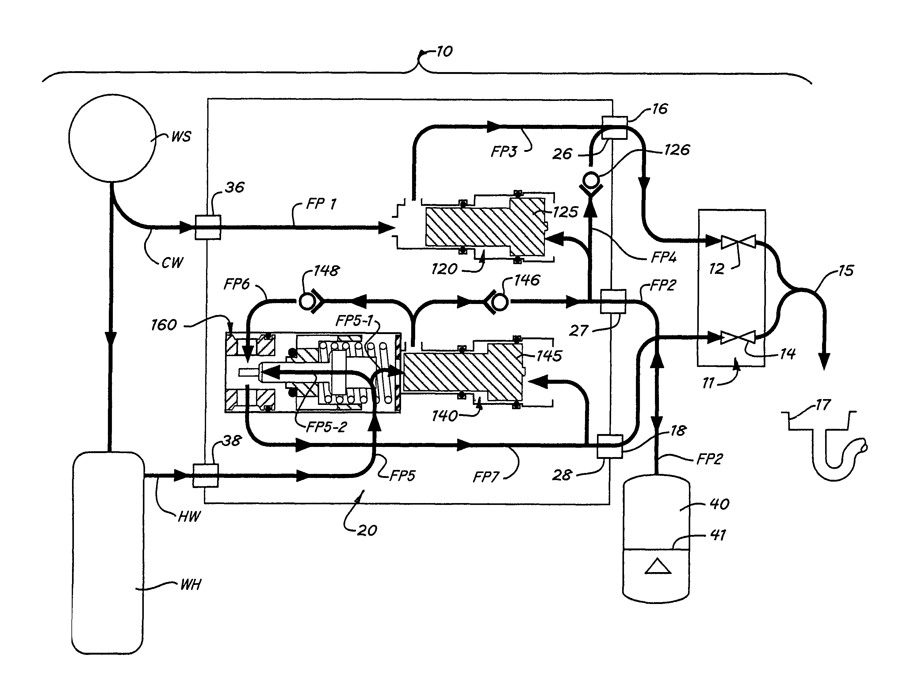
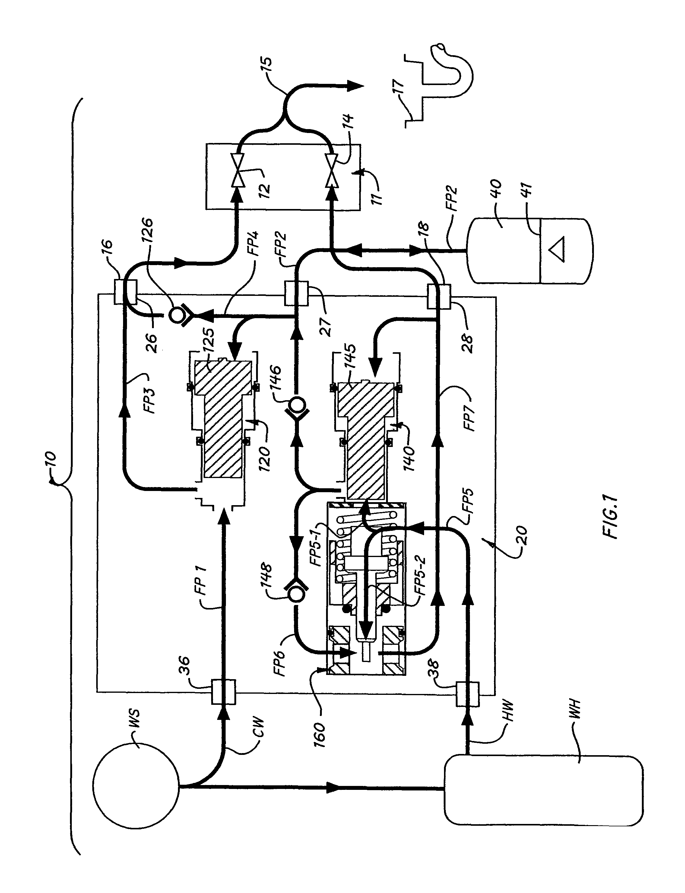
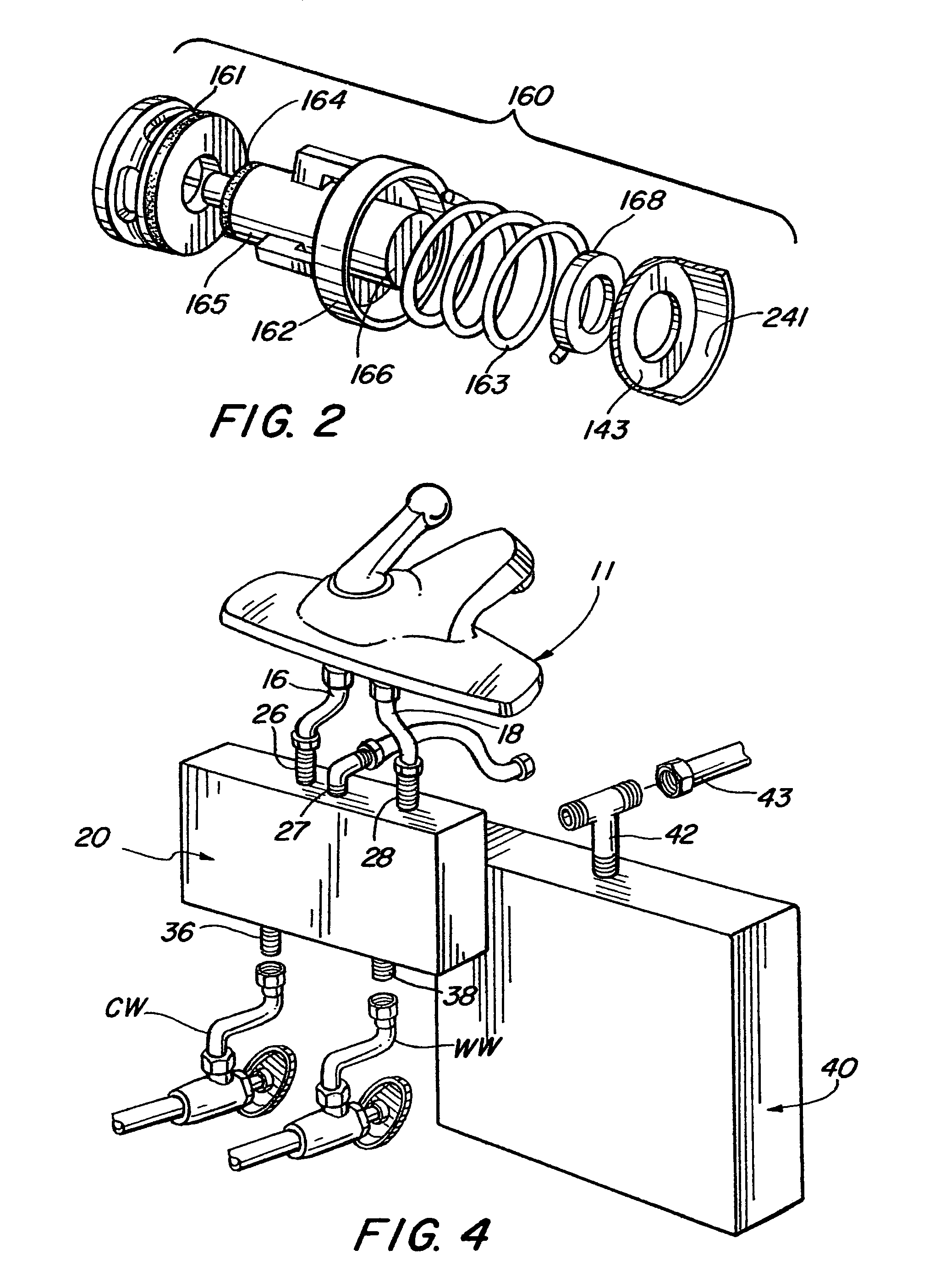
[0027]As shown in FIGS. 1-4, the inventive water conservation system, generally designated by the numeral 10, comprises a conventionally implemented faucet assembly 11 provided with a cold water valve 12 and a hot water valve 14 each conventionally conformed for connection by known water tight connectors 16 and 18 either directly to the local water supply WS or to the outlet of a conventional water heater WH that form the corresponding cold water and hot water plumbing branches CW and HW running through a household. By well known conventional practice valves 12 and 14 are either coordinated for operation by a single, manually articulated lever or by individually associated mechanisms that control the flow therethrough into a common outlet 15.

[0028]Of course, ordinary prudence demands that all excess flow from each faucet assembly be confined by a tub, sink basin, shower pan or the like, and conveyed through a drain 17 into the sewer. In conventional practice this excess flow also in...


PUM


Abstract

A unitary valve block assembly is interposed between a hot and cold water outlet and a faucet assembly including a hot and cold valve to convey the initially cold portion from the hot water outlet into an accumulator during all the times when the accumulator is substantially unfilled. This accumulated water is then emitted through the cold water valve each time cold water is demanded. When the pressure ratio between the accumulator and the water source indicates that it contains substantial quantities of un-evacuated stored water the subsequent demands of hot water are conveyed directly to the hot water valve regardless of the temperature thereof.

Description

BACKGROUND OF THE INVENTION[0001]1. Field of the Invention[0002]The present invention relates to an apparatus and method for collecting and thereafter recycling the initially cold portion of a household hot water stream that is usually wasted, and more particularly to a temperature sensing water flow diversion circuit that directs the initially cold part of the hot water flow into an accumulator for subsequent cold water use.[0003]2. Description of the Prior Art[0004]With increasing population density prudence in the use of the world's resources has become a dominant concern. One resource that is central to all the functions of life is potable water, a resource that is growing scarce and is therefore now the primary concern of most municipalities. Simply, the availability of fresh water now limits most municipal growth and virtually all housing expansions are currently associated with costly water recycling or conservation measures, a cost exchange that will only continue to rise in...

Claims


Application Information

Patent Timeline
Patent Type & Authority Patents(United States)
IPC IPC(8): G05D23/12F16K49/00G05D23/185F16L53/00
CPCE03B1/04E03B1/048E03C1/00E03B7/045Y10T137/0318Y10T137/6497Y10T137/7737Y10T137/2577
Inventor GREENTHAL, STEVEN M.SMITH, NEAL W.
Owner NITROWORKS CORP
Why Eureka
Try Eureka