Automatic transmission fluid filter

a transmission fluid and filter technology, applied in the direction of filtration separation, lubricant mounting/connection, separation process, etc., can solve the problems of significant deterioration of the case appearance, performance deterioration, poor outer appearance, etc., to improve the flowability of resin during the molding process, improve the rigidity, and uniform wall thickness

Active Publication Date: 2012-08-21
TOYOTA BOSHOKU KK
View PDF58 Cites 15 Cited by
  • Summary
  • Abstract
  • Description
  • Claims
  • Application Information

AI Technical Summary

Benefits of technology

[0007]The embodiments of the present invention are provided to address the problems with the conventional technology above. An advantage of the embodiments of the present invention is to provide an aesthetically pleasing automatic transmission fluid filter designed to be able to have improved case rigidity and fabrication properties as well as to be able to reduce pressure loss during use of the filter.
[0012]In the automatic transmission fluid filter according to the present embodiments, at least one of the cases includes a pair of joint portions respectively joined to the opposite walls of the holder frame, and a connecting wall connecting the pair of joint portions and having a circular arc longitudinal cross section protruding outward of one case, so that the cases need not be provided with any ribs on the inner surfaces and yet can have enhanced rigidity due to the connecting wall having a circular arc longitudinal cross section. The cases have a substantially uniform wall thickness so that resin flowability during the case molding process is improved, as well as the amount of use of resin can be reduced, i.e., the case fabrication properties can be improved. Also, the fluid inside the cases will have better flow properties during the use of the filter so that the pressure loss can be reduced. Further, the cases have a good appearance.
[0013]If the pair of joint portions are formed to respectively include a first lateral wall, a vertical wall, and a second lateral wall, and the outer ends of the connecting wall are connected to the inner ends of the second lateral walls, the stress locally applied on the cases by the vertical walls can be dispersed and the points of stress can be distanced from the first lateral walls, whereby the rigidity (in particular, joint strength) of the cases can be further improved. Since the first lateral walls can be joined to the walls of the holder frame in a state in which the first lateral walls and second lateral walls are pressed down with jigs, the case fabrication properties can be further improved. When the first lateral walls and the second lateral walls are pressed down with the jigs, the first lateral walls can conform to the walls of the holder frame due to flexure of the vertical walls, which contributes to a further improvement in the case fabrication properties.
[0014]If the pair of joint portions are formed to respectively include a first lateral wall and a vertical wall, and the outer ends of the connecting wall are connected to the distal ends of the vertical walls, the stress locally applied on the cases by the vertical walls can be dispersed and the points of stress can be distanced from the first lateral walls, whereby the rigidity (in particular, joint strength) of the cases can be further improved.
[0015]If one of the cases is made of a laser transmitting resin, while the holder frame is made of a laser absorbing resin, and the joint portions are joined to the walls of the holder frame by laser welding, the case can be easily joined to the holder frame and can have a good appearance even though a transparent or translucent material is employed for the case.

Problems solved by technology

These ribs 107 prevent deformation of the case toward the filter element due to suction negative pressure and a consequent increase in pressure loss, which will lead to performance deterioration.
However, with the conventional automatic transmission fluid filter mentioned above, sink marks easily occur during the case molding process because of the plurality of internally formed ribs 107 of the cases 102 and 103, resulting in poor outer appearance.
The case appearance is significantly deteriorated, in particular, when a case that is transparent or translucent is joined with the holder frame by laser welding.
The ribs also cause an increase in the amount of use of resin which leads to a higher production cost.
Another problem was that the ribs have a large impact on the flow properties of a fluid flowing through the filter chamber during use, causing an increase in pressure loss.

Method used


Image

  • Automatic transmission fluid filter
  • Automatic transmission fluid filter
  • Automatic transmission fluid filter

Examples


example

[0034]The present invention will be hereinafter described more specifically by way of examples of embodiment using the drawings. The “automatic transmission fluid filter” according to the invention is herein exemplified as an oil filter.

[0035](1) Structure of the Oil Filter

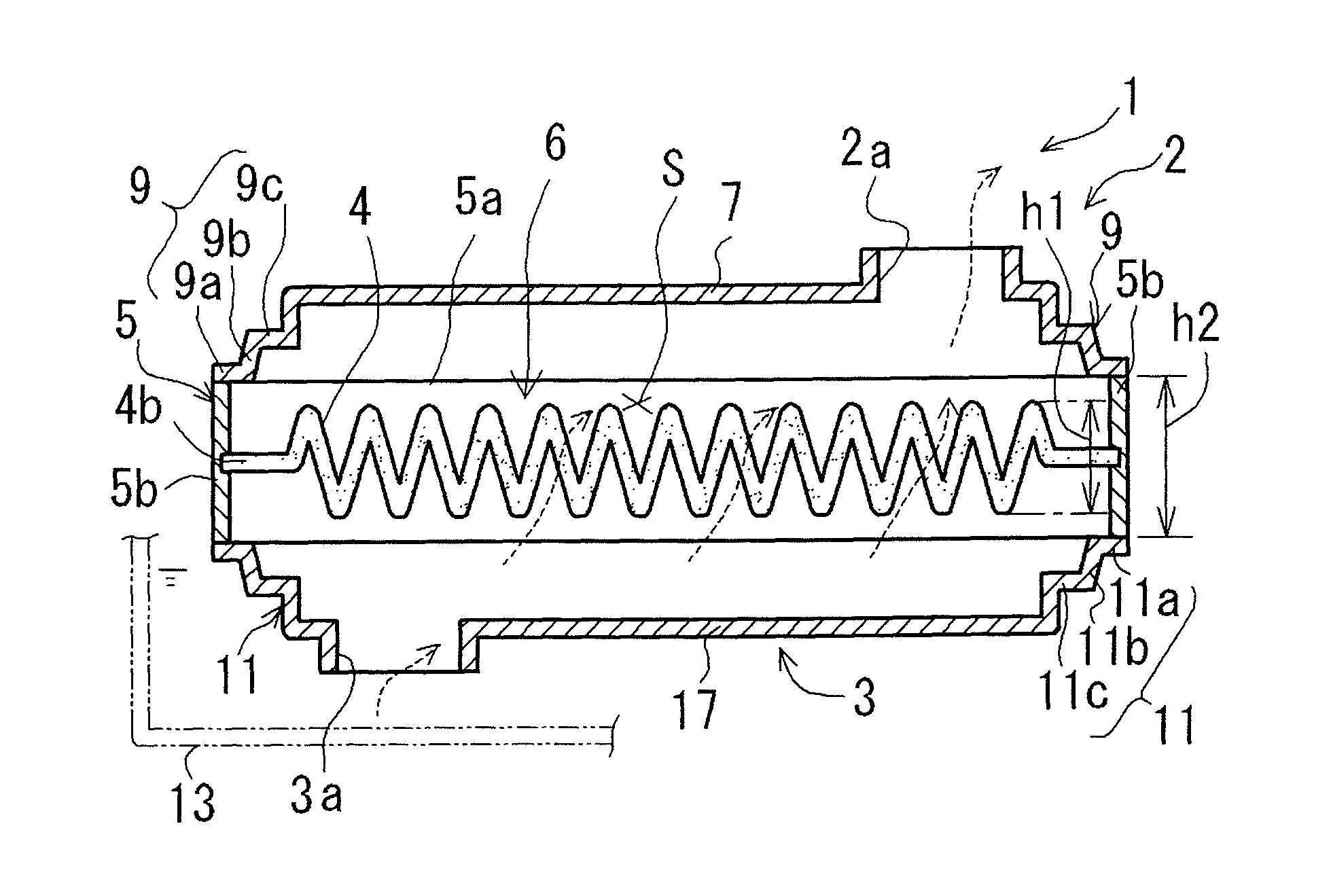
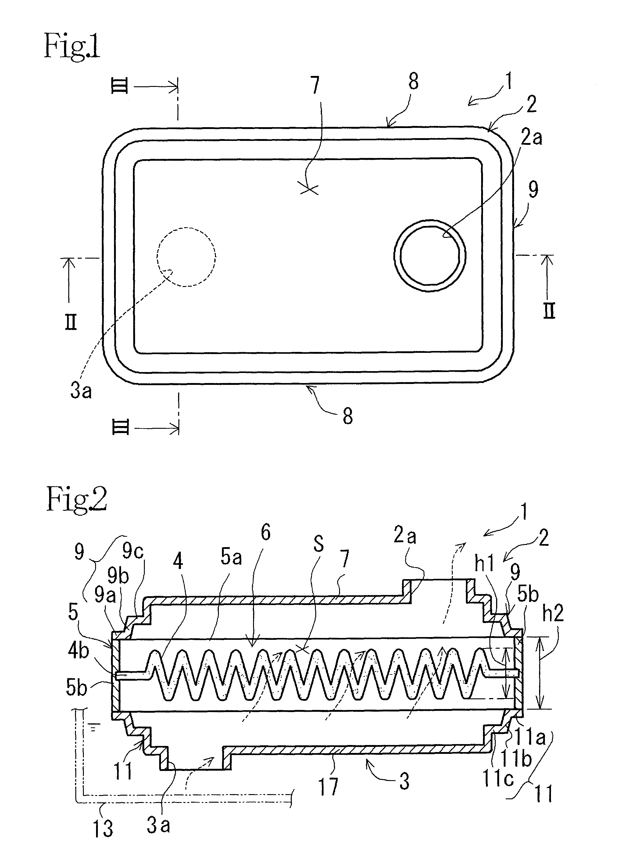
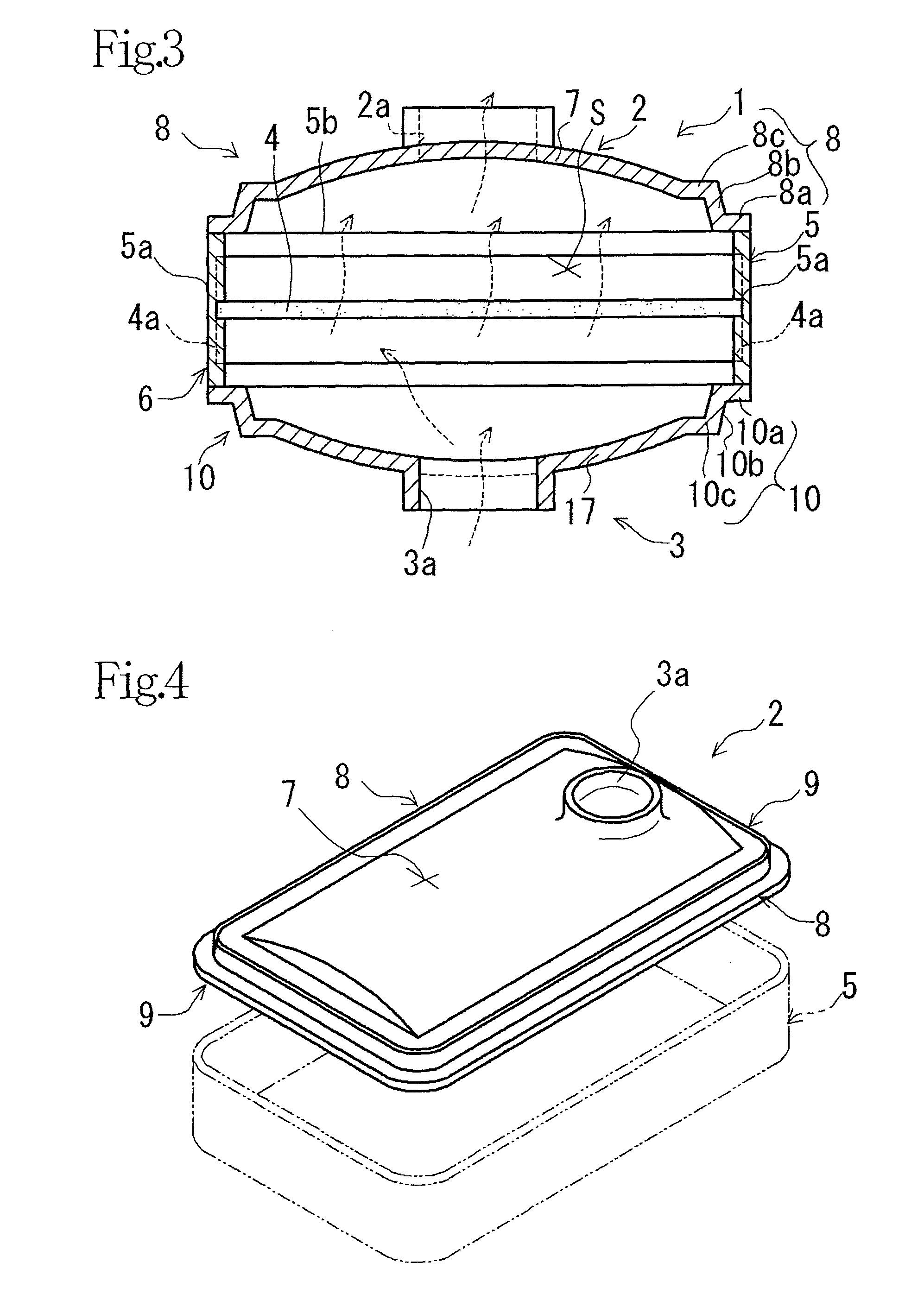
[0036]The oil filter 1 according to this example embodiment includes an upper case 2 made of a laser transmitting resin and having an outlet port 2a, a lower case 3 made of a laser transmitting resin and having an inlet port 3a, and a filter element 6 including a filter medium 4 and a holder frame 5 made of a laser absorbing resin, holding the periphery of the filter medium 4 and held between the upper case 2 and the lower case 3, as shown in FIG. 1 to FIG. 4. These upper case 2 and lower case 3 are respectively formed to be substantially rectangular in plan view.

[0037]The filter element 6 is integrally formed with the filter medium 4 and holder frame 5 by insertion molding. This filter medium 4 is formed substant...


PUM

PropertyMeasurementUnit
radius of curvatureaaaaaaaaaa
heightaaaaaaaaaa
rigidityaaaaaaaaaa

Abstract

The automatic transmission fluid filter includes a plastic upper case having an outlet port, a plastic lower case having an inlet port, and a filter element including a filter medium and a plastic holder frame holding the periphery of the filter medium and held between the upper case and lower case, at least one of the upper case and lower case including a pair of joint portions respectively joined to opposite walls a of the holder frame, and a connecting wall connecting the pair of joint portions and having a circular arc longitudinal cross section protruding outward of one case.

Description

CROSS-REFERENCE TO RELATED APPLICATIONS[0001]The present application claims priority under 35 U.S.C. §119 of Japanese Application No. 2010-101471 filed on Apr. 26, 2010, the disclosure of which is expressly incorporated by reference herein in its entirety.BACKGROUND OF THE INVENTION[0002]1. Field of the Invention[0003]The present invention relates to an automatic transmission fluid filter, and more particularly to an aesthetically pleasing automatic transmission fluid filter designed to be able to have improved case rigidity and fabrication properties as well as to be able to reduce pressure loss during use of the filter.[0004]2. Description of Related Art[0005]A commonly known conventional automatic transmission filter includes, for example as shown in FIG. 10, an upper case 102 having an outlet port 102a, a lower case 103 having an inlet port 103a, and a filter element 106 including a filter medium 104 and a holder frame 105 holding the periphery of the filter medium 104 and held ...

Claims


Application Information

Patent Timeline
Patent Type & Authority Patents(United States)
IPC IPC(8): B01D29/07B01D35/30B01D35/027
CPCB01D29/111B01D35/0273B29C65/1635B29C66/30223B29C66/112B29C66/114B29C65/06B29C65/08B29C65/20B29C66/5432B29L2031/14B29C65/1677B29C65/48B29C66/8322B29C66/7392B29K2995/0027
Inventor SAKATA, HARUAKISAITO, YASUHIROMORI, TOSHIAKI
Owner TOYOTA BOSHOKU KK
Why Eureka
Try Eureka