Printed circuit boards including strip-line circuitry and methods of manufacturing same

a technology of printed circuit boards and strip-line circuits, which is applied in the direction of printed circuit non-printed electric components association, waveguide type devices, waveguides, etc., can solve the problems of affecting the operation of microstrip transmission lines, affecting the performance of circuits, and strip-line is more complex to fabricate than microstrips, so as to improve fabrication and assembly techniques, reduce time, complexity and/or cost of strip-line fabrication operations, the effect of improving the quality of strip

Inactive Publication Date: 2014-07-01
TYCO HEALTHCARE GRP LP
View PDF22 Cites 1 Cited by
  • Summary
  • Abstract
  • Description
  • Claims
  • Application Information

AI Technical Summary

Benefits of technology

[0020]A continuing need exists for methods of manufacturing strip-line circuits with improved fabrication and assembly techniques. A continuing need exists for strip-line configurations on printed circuit boards at lower costs. There is a need for methods of reducing the time, complexity and / or cost of strip-line fabrication operations and / or printed circuit board inspection, test, and / or rework. There is a need for methods of manufacturing printed circuit boards that allow access to components assembled into strip-line configurations.

Problems solved by technology

Microstrip transmission line operation may be impaired by stray electromagnetic coupling between the line conductor and nearby objects.
Fringing of the electromagnetic fields that extend above the line conductor to foreign objects may introduce irregularities into the impedance and velocity factor of the line, with a resultant negative effect on circuit performance.
Strip-line transmission lines offer some electrical performance advantages compared to microstrip, but strip-line is more complex to fabricate than microstrip.

Method used


Image

  • Printed circuit boards including strip-line circuitry and methods of manufacturing same
  • Printed circuit boards including strip-line circuitry and methods of manufacturing same
  • Printed circuit boards including strip-line circuitry and methods of manufacturing same

Examples


Embodiment Construction

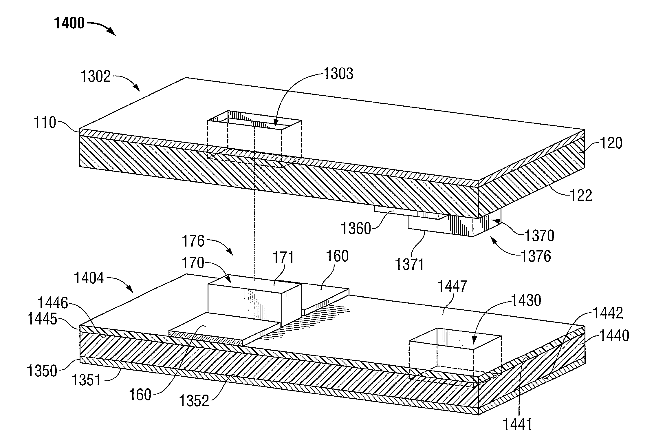
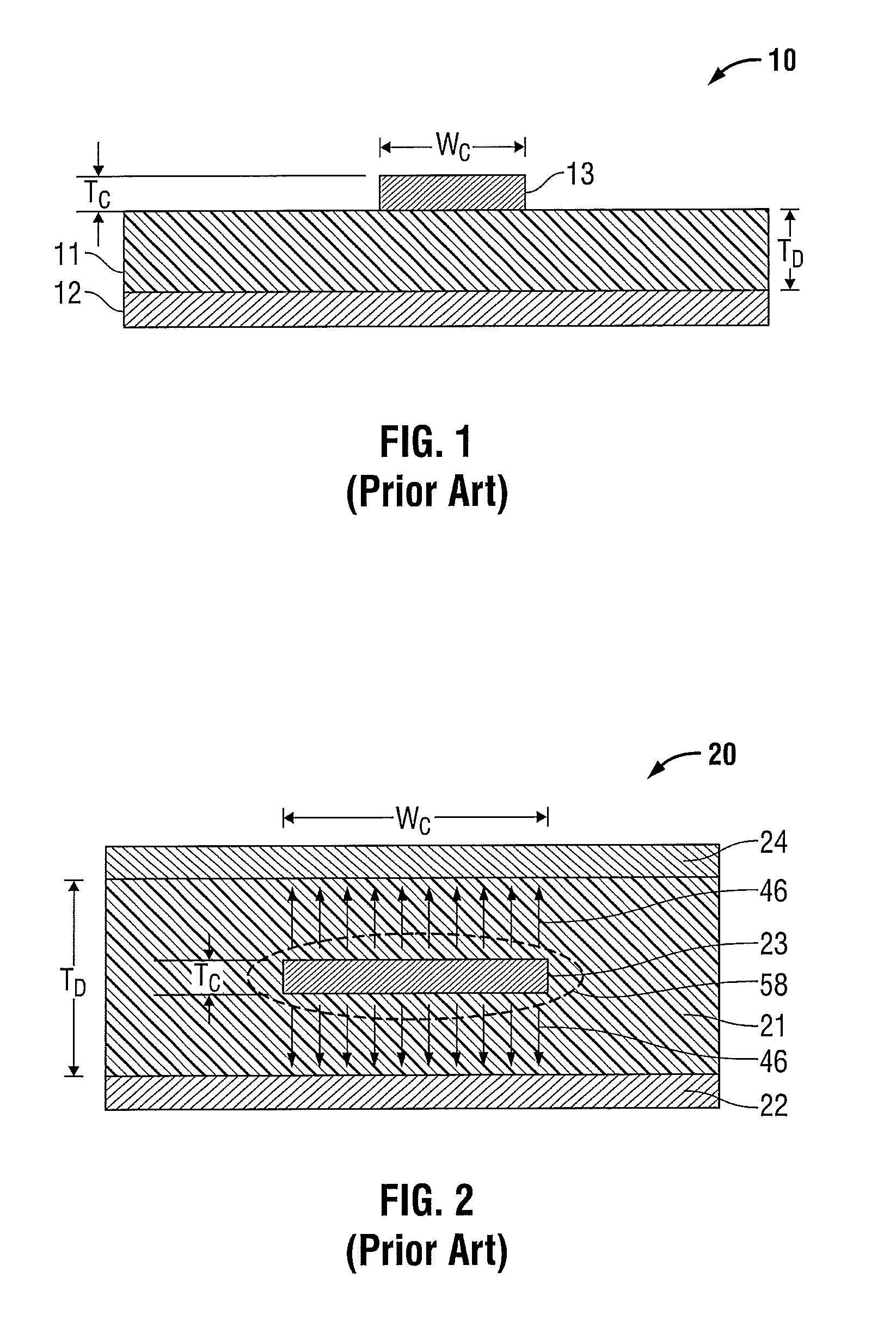
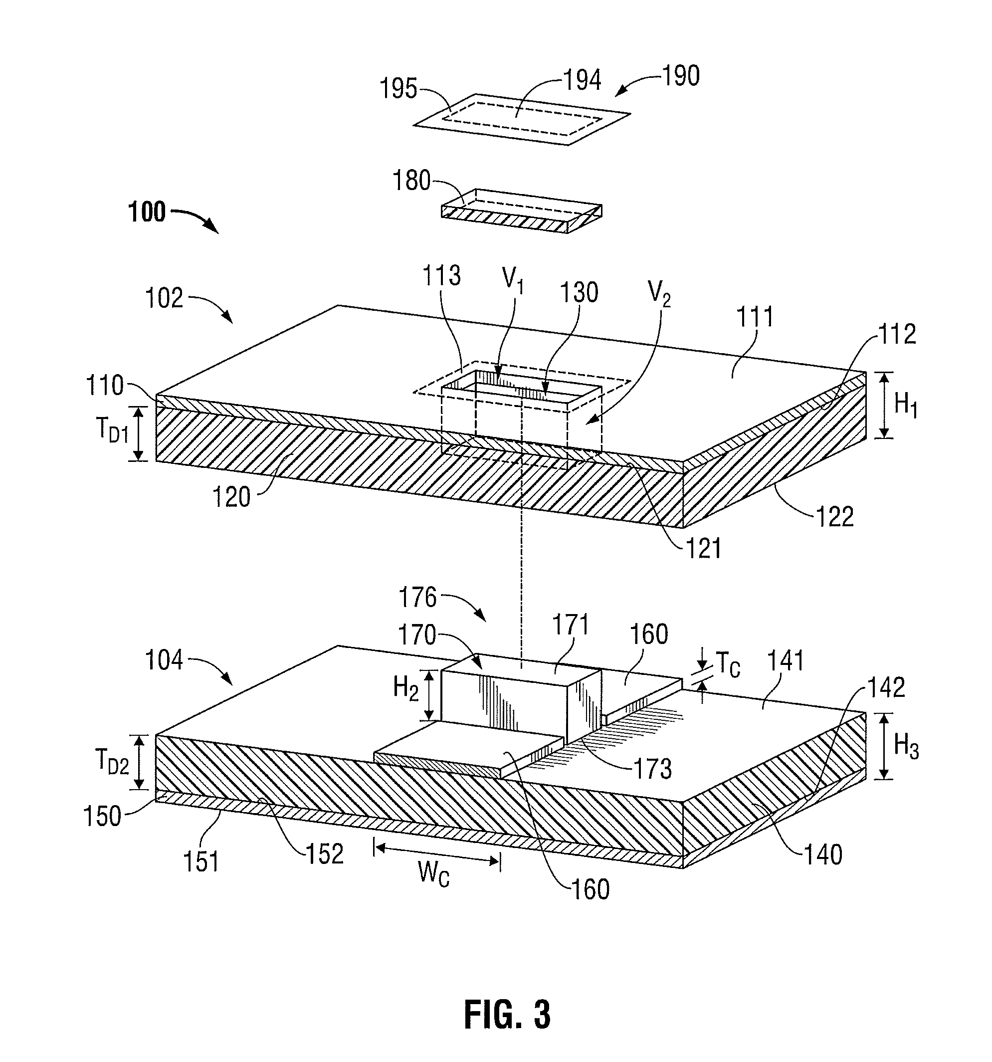
[0073]Hereinafter, embodiments of the presently-disclosed printed circuit boards including strip-line circuitry and methods of manufacturing the same are described with reference to the accompanying drawings. Like reference numerals may refer to similar or identical elements throughout the description of the figures. As shown in the drawings and as used in this description, and as is traditional when referring to relative positioning on an object, the term “proximal” refers to that portion of the device, or component thereof, closer to the user and the term “distal” refers to that portion of the device, or component thereof, farther from the user.

[0074]This description may use the phrases “in an embodiment,”“in embodiments,”“in some embodiments,” or “in other embodiments,” which may each refer to one or more of the same or different embodiments in accordance with the present disclosure. For the purposes of this description, a phrase in the form “A / B” means A or B. For the purposes o...


PUM

PropertyMeasurementUnit
dielectric constantaaaaaaaaaa

Abstract

A multi-layer printed circuit board includes a first layer stack and a second layer stack coupled to the first layer stack. The first layer stack includes a first electrically-insulating layer, a second electrically-insulating layer, and a first electrically-conductive layer disposed between the first and second electrically-insulating layers. The second layer includes a third electrically-insulating layer and a second electrically-conductive layer. The first layer stack and / or the second layer stack include a cut-out area defining a void that extends therethrough. The multi-layer printed circuit board further includes a first signal layer disposed in association with the first electrically-insulating layer of the first layer stack or the third electrically-insulating layer of the second layer stack, a second signal layer disposed in association with the second electrically-insulating layer of the first layer stack, and a device at least partially disposed within the cut-out area and electrically-coupled to the first and second signal layers.

Description

BACKGROUND[0001]1. Technical Field[0002]The present disclosure relates to strip-line circuitry. More particularly, the present disclosure relates to printed circuit boards including strip-line circuitry and methods of manufacturing the same.[0003]2. Discussion of Related Art[0004]Commonly used techniques for circuit and / or system interconnect include microstrip and strip-line transmission lines. In a simple representation, as shown in FIG. 1, a microstrip transmission line consists of a conductive trace 13 of controlled width WC disposed on a low-loss dielectric 11 which is, in turn, disposed on a ground-plane layer 12. In microstrip there is one ground plane, while in strip-line, there are two.[0005]Microstrip and strip-line transmission lines can be fabricated using printed circuit board technology. Printed circuit boards (PCBs), sometimes referred to as printed wiring boards (PWBs) or etched wiring boards, are widely used in the assembly of discrete electrical components into ope...

Claims


Application Information

Patent Timeline
Patent Type & Authority Patents(United States)
IPC IPC(8): H05K1/18H05K3/46H05K1/16
CPCH01P3/088H01P11/003Y10T29/49124H05K2203/063H05K2201/0969H05K2201/0715H05K1/025H05K1/0225H05K1/0231H05K3/4694H05K2201/066H05K1/0243H05K1/183H05K3/4611H05K2201/0723H05K1/186H05K1/0298
Inventor MOUL, WAYNE L.BEHNKE, II, ROBERT J.FRUSHOUR, SCOTT E. M.JENSEN, JEFFREY L.
Owner TYCO HEALTHCARE GRP LP
Why Eureka
Try Eureka