Tag detecting system, moving object detecting method, and entrance/exit management system

a technology of tag detection and management system, applied in the direction of electrical programme control, program control, instruments, etc., can solve the problems of system difficult to use outside, prone to influence, and reduce the accuracy of detecting a position

Active Publication Date: 2012-08-21
HITACHI ENG & SERVICES CO LTD +2
View PDF31 Cites 15 Cited by
  • Summary
  • Abstract
  • Description
  • Claims
  • Application Information

AI Technical Summary

Benefits of technology

[0011]According to the present invention, the tag detecting system capable of detecting the specific object or person by narrowing the detection area of the RFID tag in a simple system construction, the moving object detecting method, and the entrance / exit management system realized by the moving object detecting system thereof, are provided.

Problems solved by technology

However, a system for detecting the entrance to and the exit from the facility by the active tag, is liable to be influenced by a wave reflector and an obstacle surrounding the system.
These drawbacks reduce accuracy for detecting a position and make the system difficult used outside.
Hereby, a problem is that the method is liable to be influenced by an external light.
In case of a high-frequency magnetic field method, since the transmitting range thereof extends in a spherical shape, a problem is that a tag detection range becomes too broad.
As a result, after a person (or an object) having the RFID tag is certified and passes through a gate, if a person having no RFID tag adjacently passes through the gate (so called a piggyback), the conventional method has no means to detect the piggyback because the detection range is unstable or too broad.

Method used


Image

  • Tag detecting system, moving object detecting method, and entrance/exit management system
  • Tag detecting system, moving object detecting method, and entrance/exit management system
  • Tag detecting system, moving object detecting method, and entrance/exit management system

Examples


first embodiment

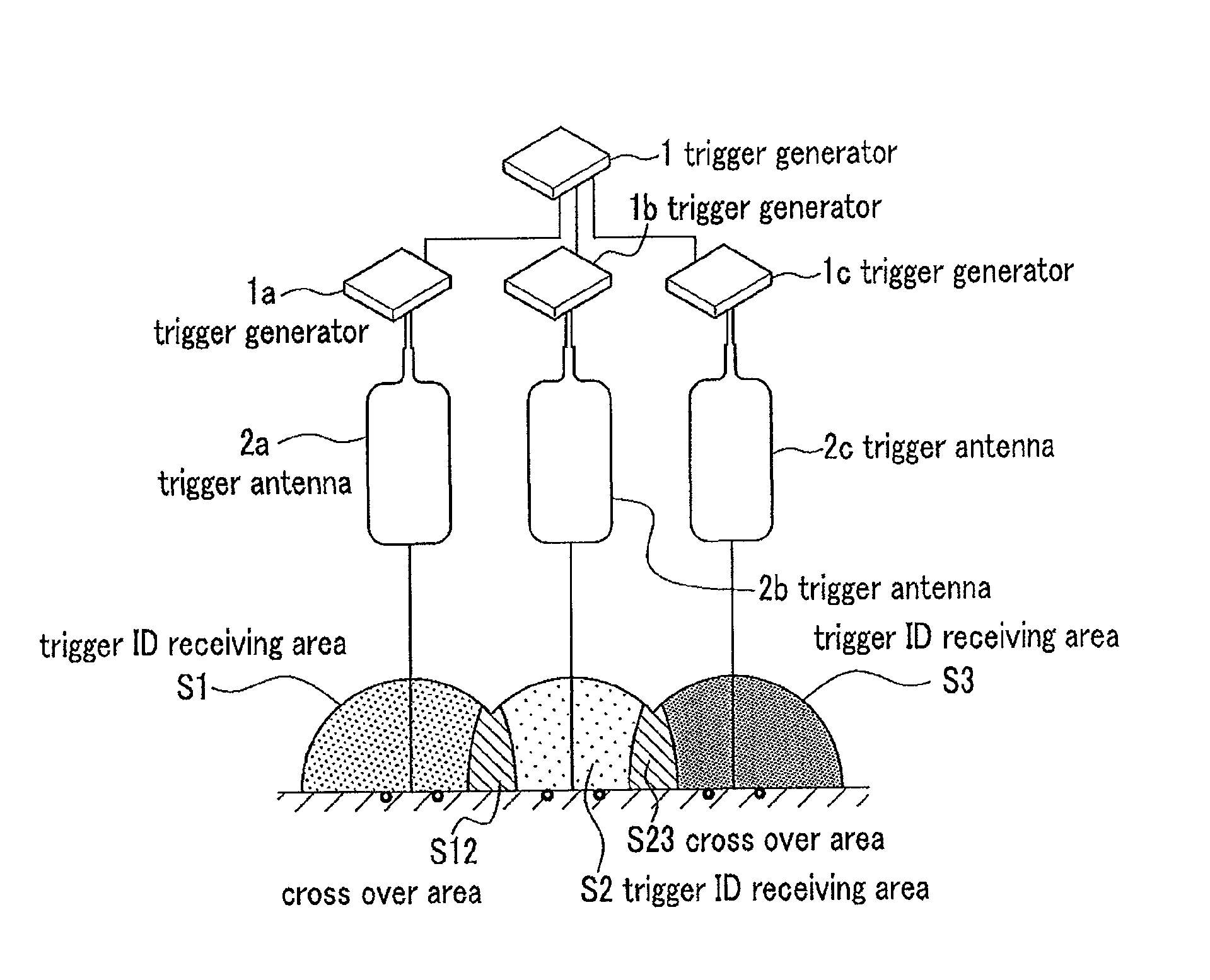
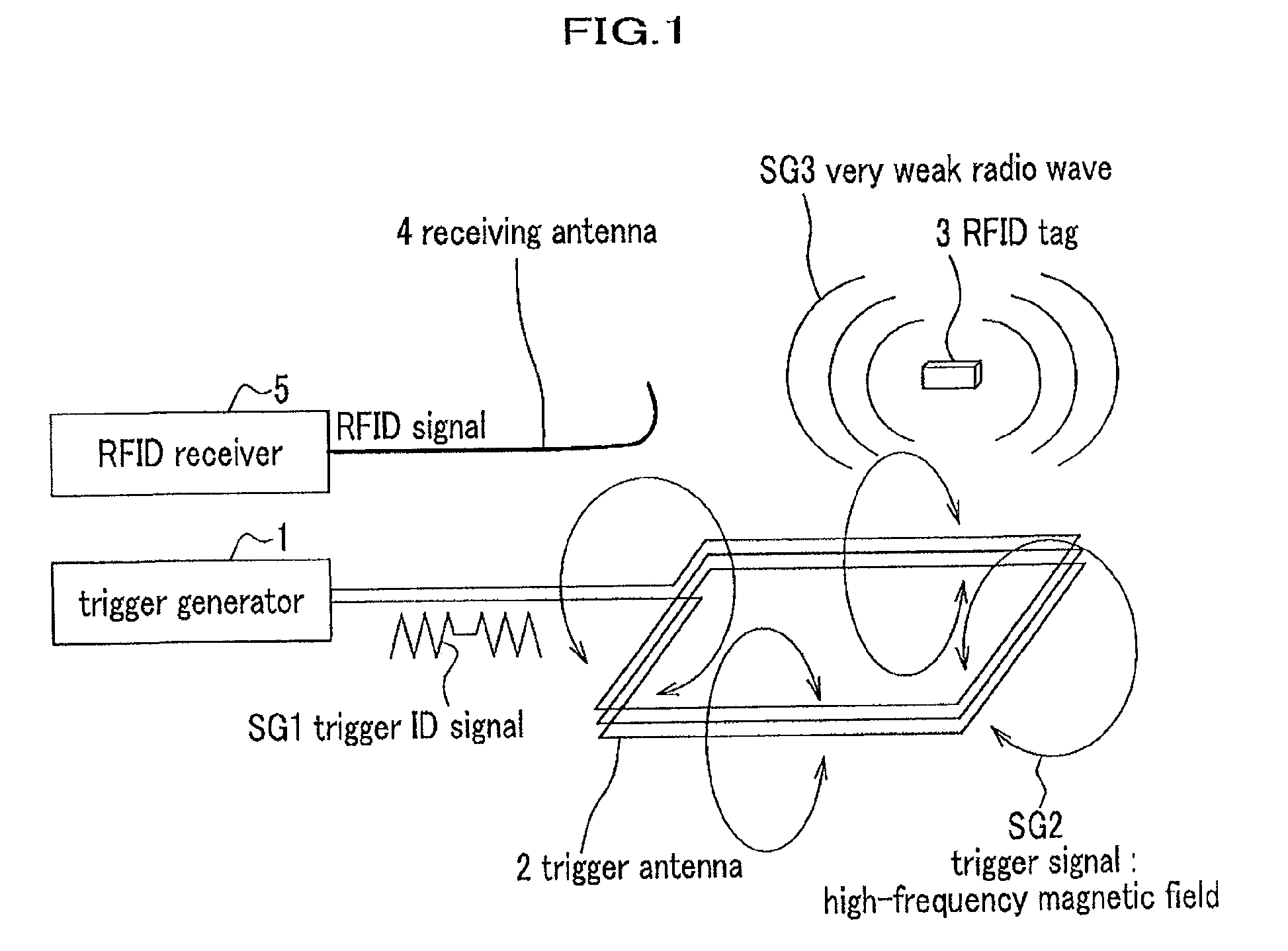
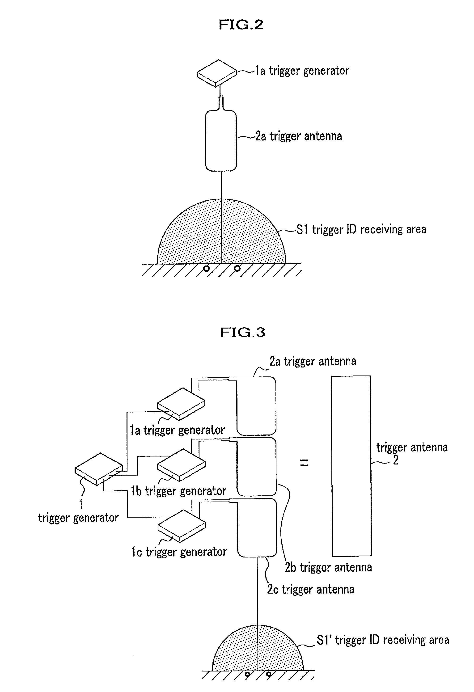
[0047]First, in reference to FIG. 1 mentioned hereinbefore, a process that a three-dimensional coil (3D coil) incorporated in the RFID tag 3 detects a three-dimensional high frequency magnetic field which is generated in directions of X, Y, and Z, and a receiving area in a high-frequency magnetic field is restricted will be explained. If the trigger generator 1 generates a pulse code modulated signal by an OOK method (On-Off-Keying: two values modulation method) or an ASK method (Amplitude Shift Keying: amplitude shift modulation method), the trigger antenna 2 generates a high-frequency magnetic field SG2 containing a pulse code modulated signal. Here, if a plurality of the trigger generators 1 and trigger antennas 2 are adjacently arranged, not shown in FIG. 1, the high-frequency magnetic field SG2 having a cross over area in which high-frequency magnetic fields are overlaid, is generated (see FIG. 5).

[0048]On the other hand, the RFID tag 3 detects the high-frequency magnetic field...

second embodiment

[0058]FIG. 8 is a model diagram showing a pulse code modulated signal used for the entrance / exit management system of the present invention. As shown in FIG. 8, a trigger ID signal of the high-frequency magnetic field emitted from the trigger antenna 2 in FIG. 1 to the RFID tag 3 in the high-frequency magnetic field (that is, a pulse code modulated signal) includes a preamble part 21 which is a continuous wave in a definite period, a succeeding header part 22, and a data part 23. If the IC 7 in the RFID tag 3 detects the trigger signal by the preamble part 21, the IC 7 starts to prepare for receiving the data part 23. Then, if the RFID tag 3 confirms the header part 22 followed by the preamble part 21, the RFID tag 3 starts to receive the succeeding trigger signal as a data part. In other words, the IC 7 in the RFID tag 3, can output an amplitude modulated magnetic field as a change in a voltage. Further, the IC 7 has a function capable of outputting only the data which includes a s...


PUM


Abstract

A tag detecting system for detecting a movement of a person or an object that mounts an RFID tag, a moving object detecting method, and an entrance / exit management system using the moving object detecting system are provided. The tag detecting system detects a specific person or object by restricting a detection area of the RFID tag to a narrow area. Since the moving object detecting method detects a piggyback, the entrance / exit system prevents the piggyback even if there are a number of persons passing through an entrance / exit gate almost at the same time.

Description

BACKGROUND OF THE INVENTION[0001]1. Field of the Invention[0002]The present invention relates to a tag detecting system for detecting a movement of an object mounting an RFID tag, a moving object detecting method, and an entrance / exit management system which is realized by the moving object detecting method.[0003]2. Description of Related Art[0004]Recently, an RFID tag has been widely used in buried in an IC card, or used in management systems such as an article management system and an entrance / exit management system of persons. Among the RFID tags, particularly, a semi-passive type or an active type of the RFID tag that transmits waves by a cell energy incorporated in the RFID tag, is preferably used in the entrance / exit management system of persons. The semi-passive type or the active type of the RFID tag has a quite ampler communication range (for example, 1 m-10 m) than a passive type of the RFID tag buried in the IC card.[0005]For example, an art of the entrance / exit managemen...

Claims


Application Information

Patent Timeline
Patent Type & Authority Patents(United States)
IPC IPC(8): G05B19/02H04Q5/22
CPCG01V15/00G06K7/0008G06K7/10128G06K7/10316
Inventor TAKESHIMA, MASAHIROTAMURA, KAZUOKAWAHARA, TAKESHIKONDOU, MASAYOSHIKAWARAI, DAI
Owner HITACHI ENG & SERVICES CO LTD
Why Eureka
Try Eureka