System and method to electrically ground fluid dynamic bearings

a fluid dynamic bearing and electrical ground technology, applied in the direction of casings/cabinets/drawers, casings/cabinets/drawers, instruments, etc., can solve the problems of increasing the bit error rate, increasing the concern of spurious charge buildup caused by friction, and damaging the reader, etc., to achieve low resistance, low resistance, low resistance

Active Publication Date: 2012-08-21
WESTERN DIGITAL TECH INC
View PDF24 Cites 12 Cited by
  • Summary
  • Abstract
  • Description
  • Claims
  • Application Information

AI Technical Summary

Problems solved by technology

As head-disk separation diminishes and the sensitivity of recording transducers increases, the effects of spurious charge buildup caused by friction becomes an increasing concern.
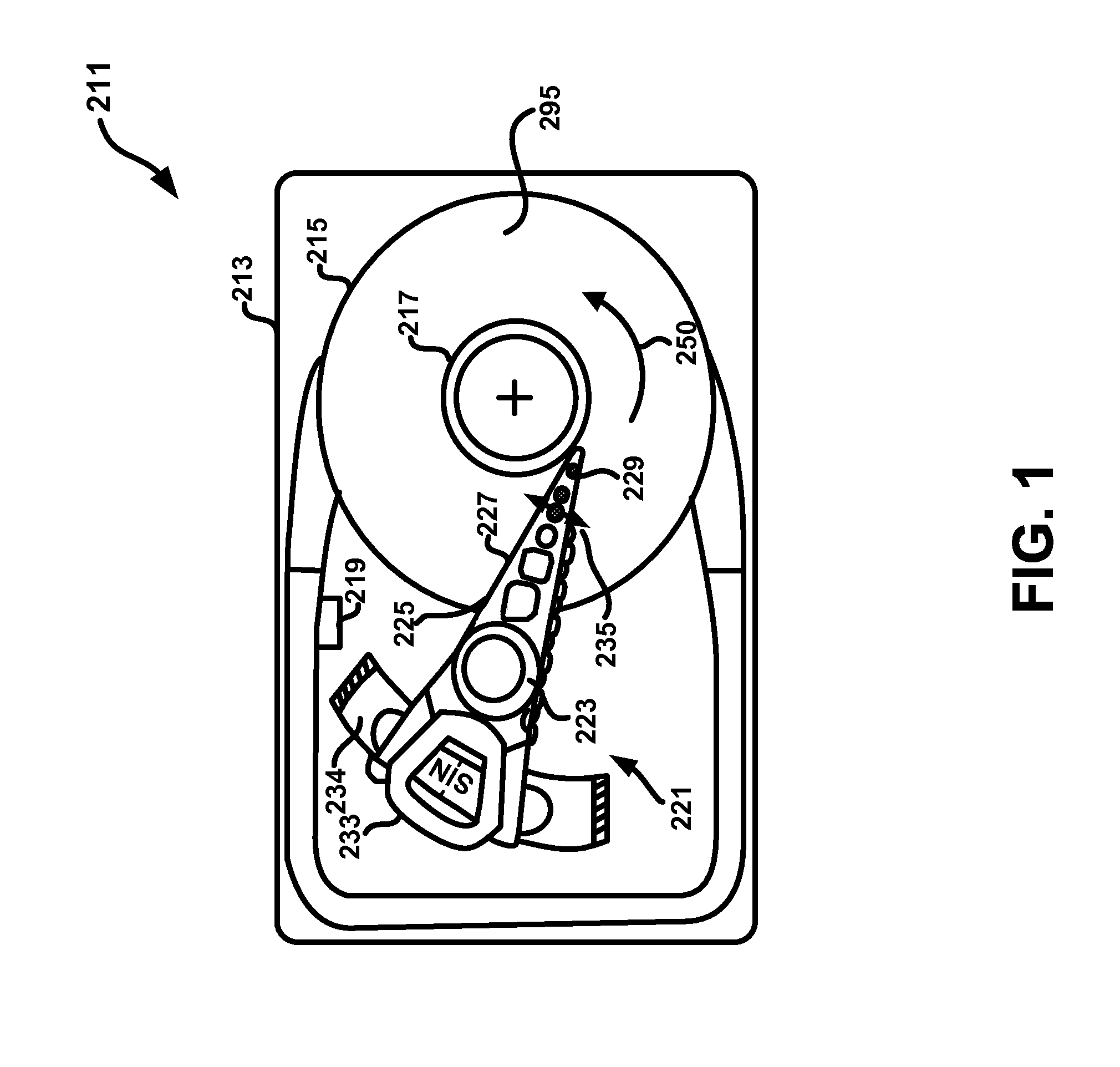
In the conventional HDD illustrated in FIG. 1A, the head to disk electrical breakdown due to inadequate grounding of the disk rotation leads to electrical noise on the disk coupling to the reader thereby increasing the bit error rate.
In the illustration in FIG. 1A, the thermal fly-height control (TFC) of the HDD is turned off and an electrical breakdown is more likely to occur between the disk and the read sensor thereby damaging the reader.
The presence of high-frequency noise transients of the disk can also degrade the bit error rate performance of the HDD.
In disk drives, the tribocharging system is complicated and involves multilayers of metal and insulators, a thin lubricant layer and complex contact surfaces.
However, this affects the performance of the fluid dynamic bearing and generally not sufficient.
Even “conductive” oils are still relatively high in resistance and therefore not a viable solution because of cost and excessive resistance.

Method used


Image

  • System and method to electrically ground fluid dynamic bearings
  • System and method to electrically ground fluid dynamic bearings
  • System and method to electrically ground fluid dynamic bearings

Examples


Embodiment Construction

[0017]Reference will now be made in detail to the alternative embodiments of the present technology. While some of the present technology will be described in conjunction with the alternative embodiments, it will be understood that they are not intended to limit the present technology to these embodiments. On the contrary, embodiments of the present technology are intended to cover alternatives, modifications and equivalents, which may be included within the spirit and scope of the embodiments as defined by the appended claims.

[0018]Furthermore, in the following detailed description, numerous specific details are set forth in order to provide a thorough understanding of embodiments of the present technology. However, it will be recognized by one of ordinary skill in the art that embodiments may be practiced without these specific details. In other instances, well known methods, procedures, components, and circuits have not been described in detail as not to unnecessarily obscure asp...


PUM

PropertyMeasurementUnit
densityaaaaaaaaaa
rotationaaaaaaaaaa
conductiveaaaaaaaaaa

Abstract

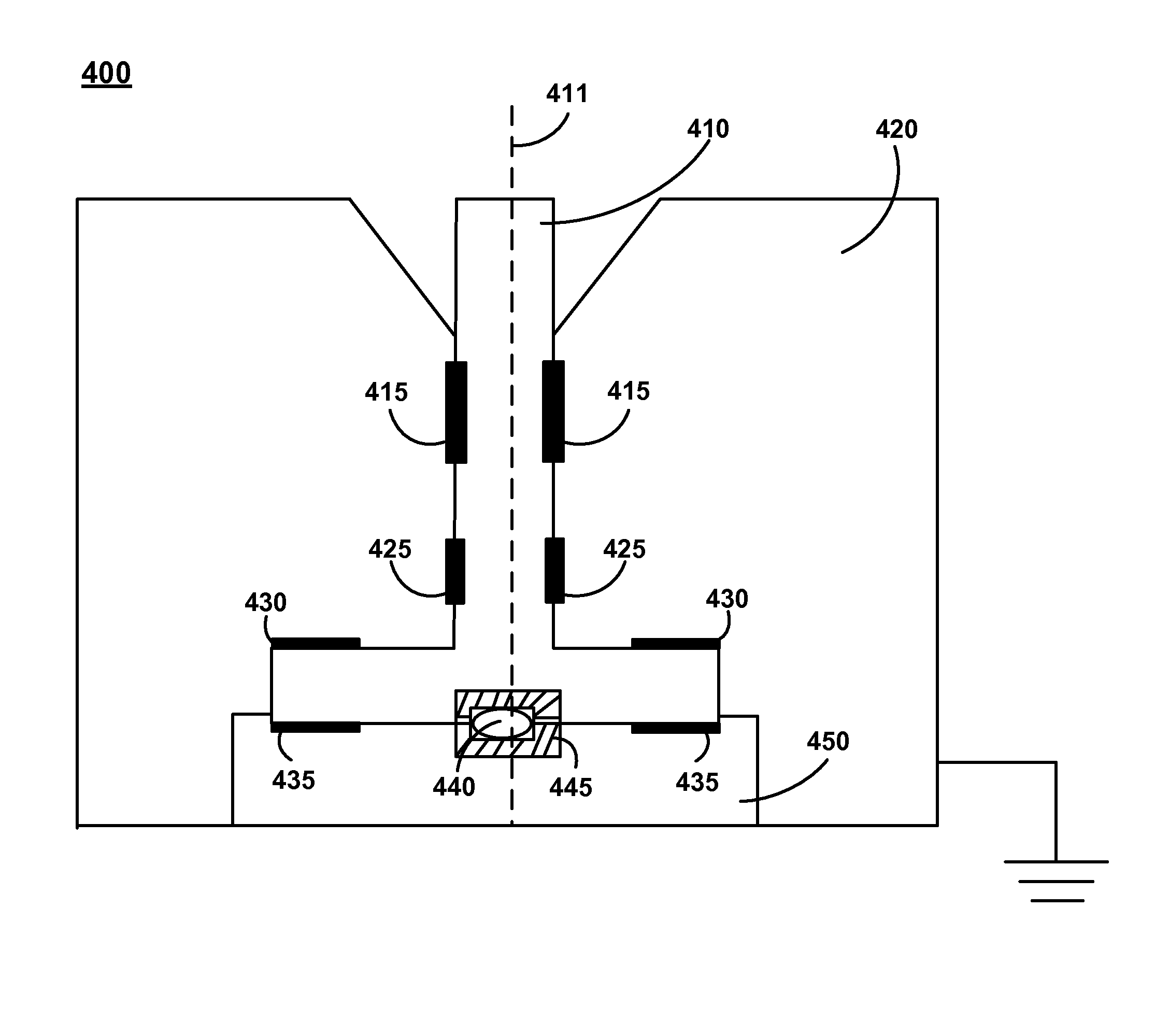
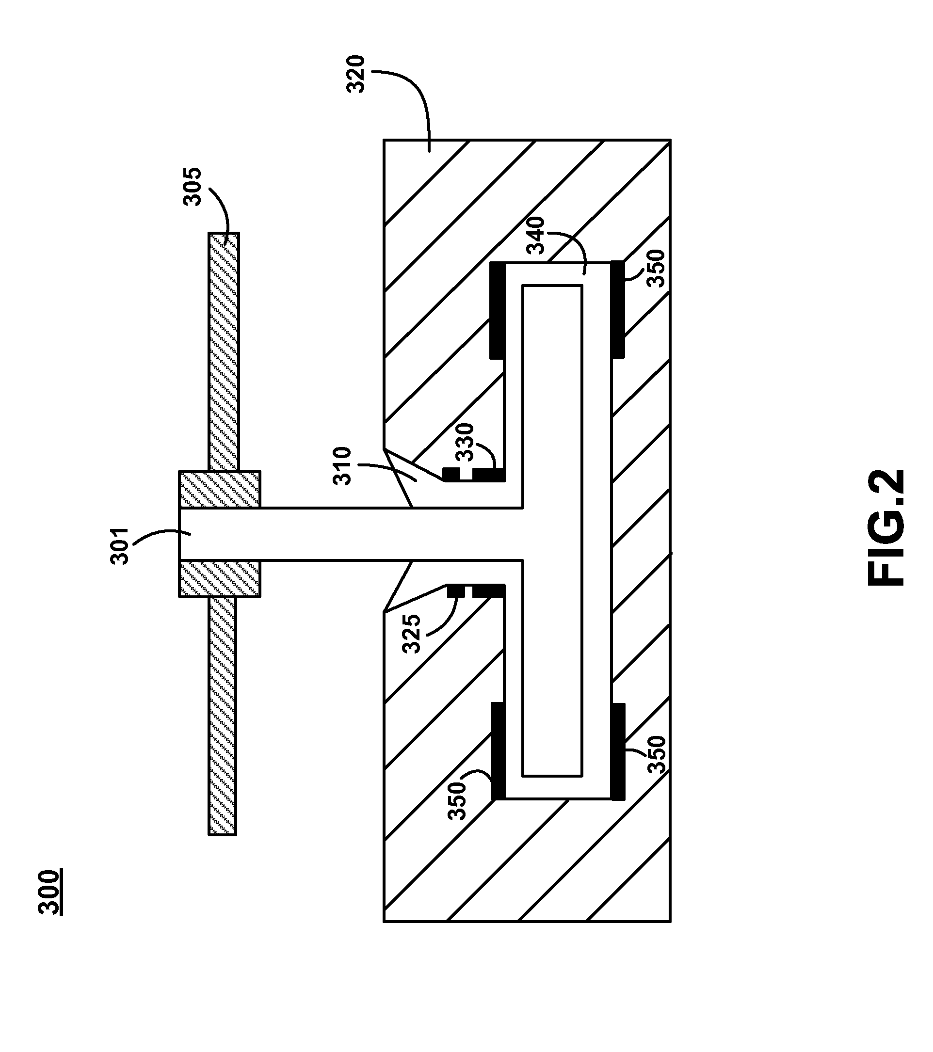
A spindle motor assembly that utilizes a fluid dynamic bearing electrically grounded to provide a conductive path through the spindle motor assembly. In one embodiment, the fluid dynamic bearing includes a liquid metal that is conductive and of low electrical resistance that provides the conductive path between the spindle and the spindle housing.

Description

TECHNICAL FIELD[0001]Embodiments of the present invention are generally related to the field of direct access data storage devices.BACKGROUND ART[0002]Hard disk drives (HDD) contain magnetic transducers that magnetize recording media and sense the magnetic field of a rotating disk. The hard disk drive design must constantly evolve to meet the increasing demand of computer applications and configurations. One component of the HDD design that has had to evolve is the spindle motor bearing. The spindle is a rod-like axle inside a HDD. The disks inside the HDD are center mounted on the spindle and the spindle and the spindle motor rotates the spindle and the disks. In the past, the majority of HDDs implemented ball bearing spindle motors. However, the HDD industry is now using a different type of bearing design known as Fluid Dynamic Bearing (FDB).[0003]FDB spindles are used because FDB spindles have significantly less runout, larger damping and lower acoustic noise. As head-disk separa...

Claims


Application Information

Patent Timeline
Patent Type & Authority Patents(United States)
IPC IPC(8): G11B17/02G11B33/14
CPCF16C17/08F16C17/107F16C17/24F16C33/103F16C33/107G11B33/1473H02K7/085H02K11/0005H02K11/01
Inventor HENDRIKS, FERDINANDWALLASH, ALBERT J.
Owner WESTERN DIGITAL TECH INC
Why Eureka
Try Eureka