Automatic image segmentation using contour propagation

a contour propagation and image segmentation technology, applied in image enhancement, image analysis, instruments, etc., can solve the problems of inability to find active contours in images, the minimum cost function may not coincide, and the image segmentation on parallel slices is typically a very time-consuming task, so as to facilitate entry and automatically propagate the contours over parallel images

Active Publication Date: 2012-08-21
MAKO SURGICAL CORP
View PDF6 Cites 52 Cited by
  • Summary
  • Abstract
  • Description
  • Claims
  • Application Information

AI Technical Summary

Benefits of technology

[0005]The techniques described herein provide methods and apparatuses for automatically segmenting contours on parallel images using contour propagation. Such automatic segmentation facilitates entering a single set of contour control points and automatically propagating the contours over parallel images.
[0020]The automatic image segmentation using contour propagation techniques described herein can provide one or more of the following advantages. An advantage of the techniques is the accurate and fast construction of a 3D surface of an object by providing a technique for automatic image segmentation with reduced algorithm complexity and less manual intervention. Manually selected edge points of a contour of a first slice can be propagated to adjacent slices and automatically used to determine the contours of the adjacent slices. Additionally, the disclosed systems and methods overcome the boundary snapping problem.

Problems solved by technology

Image segmentation on parallel slices is typically a very time consuming task.
However, Active Contour is limited in ability to find contours in images.
Additionally, the local minimum of the cost function may not coincide with a correct contour.
For example, for 80 slices, if each slice has 18 control points, the user has to click the mouse 1,440 times. In addition to the time required to manually enter control points, Live Wire may experience what is referred to as a “boundary snapping problem.” When one slice has two adjacent contours, a boundary pixel of a second adjacent contour may have a higher cost function than a boundary pixel of a first contour, and thus if the user attempts to select a pixel on the boundary of the first contour, the higher cost of a pixel on the boundary of the second contour may result in the pixel being snapped to a boundary edge of the second contour instead of the first contour.
Boundary snapping can result in an erroneous Live Wire segment unless the user selects more control points to circumvent this boundary snapping problem.

Method used


Image

  • Automatic image segmentation using contour propagation
  • Automatic image segmentation using contour propagation
  • Automatic image segmentation using contour propagation

Examples


Embodiment Construction

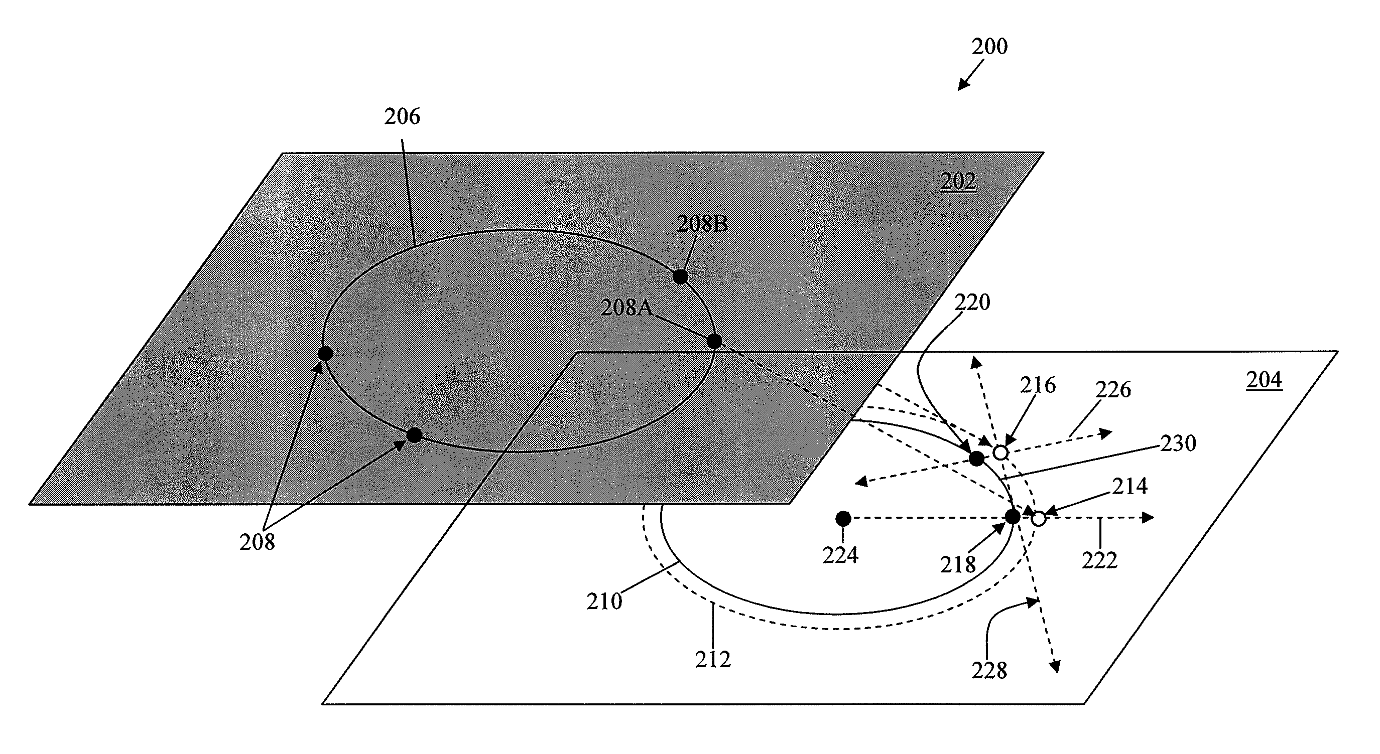
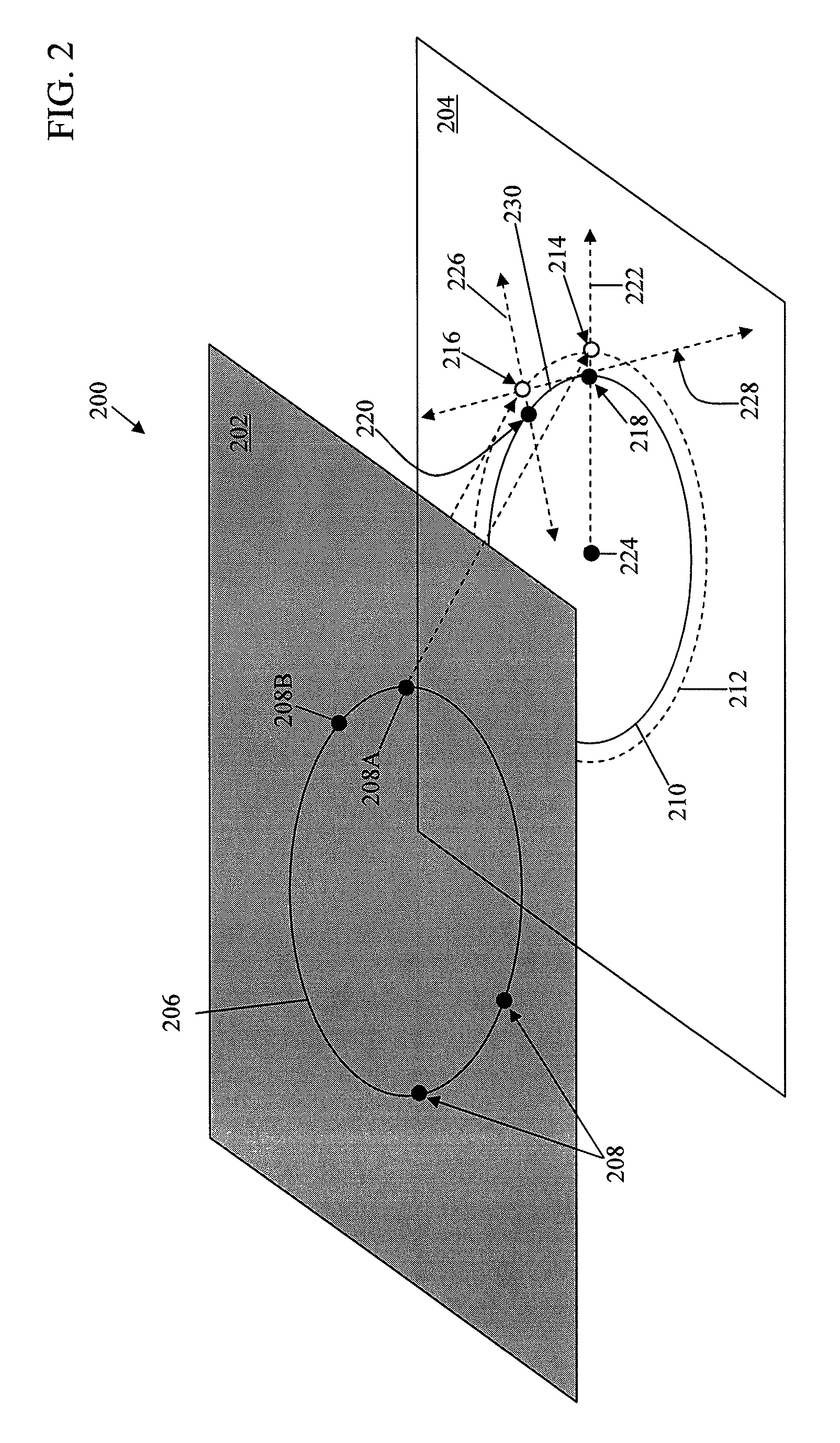
[0044]In general overview, techniques are described for automatically calculating a contour in a cross-sectional image after a set of edge points has been manually inserted into an adjacent cross-sectional image. As described in more detail below, this is done by using the manually inserted edge points as seed points for the adjacent cross-sectional image, automatically determining a plurality of paths to the seed points and other possible neighboring points using a cost function, and applying a path metric that is different from the cost function to assess each of the paths and select the optimal one based on the path metric. In these techniques, a user only needs to enter control points for a first contour of a first cross-sectional image, and the contour is automatically propagated to adjacent contours. One factor used in the path metric is the orientation changes along the path. Another factor used in the path metric is the distribution of the edge points. If the edge cost at a ...


PUM


Abstract

Described are computer-based methods and apparatuses, including computer program products, for automatic image segmentation using contour propagation. A path metric of a candidate piece of a contour in a cross-sectional image is calculated to generate a three dimensional model using a plurality of cross-sectional images of an object. Data indicative of the cross-sectional image is stored. A cost of each of a plurality of pixels associated with the candidate piece is calculated using the data, wherein the cost is representative of a likelihood the pixel is on the contour and the cost is based on one or more templates. An orientation change value is calculated for each of the plurality of pixels associated with the candidate piece based on an initial pixel of the candidate piece and the pixel. A ratio of pixels is calculated. The path metric of the candidate piece of the contour is stored, the value of the stored path metric being based on the calculated cost, the calculated orientation change value, and the calculated ratio.

Description

FIELD OF THE INVENTION[0001]The present invention relates generally to computer-based methods and apparatuses, including computer program products, for automatic image segmentation using contour propagation.BACKGROUND[0002]In image-guided therapy, such as image-guided surgery and radiation therapy planning, an accurate 3D model of human anatomy (e.g., bone, tumors, tissues, etc.) is extremely important. Cross-sectional images (commonly referred to as “slices”) of anatomical objects can be obtained using Computed Tomography (CT), Magnetic Resonance Imaging (MRI), ultrasound, and other imaging techniques. A general approach for constructing a 3D model surface of the imaged object is to connect a series of contours of human anatomy on a set of parallel or substantially parallel image slices. Image segmentation on parallel slices is typically a very time consuming task. For example, for a knee application, a user may need to segment over 80 slices, which can take 40 minutes to manually ...

Claims


Application Information

Patent Timeline
Patent Type & Authority Patents(United States)
IPC IPC(8): G06K9/46
CPCG06T7/0083G06T7/0089G06T2207/10072G06T2207/30004G06T7/12G06T7/149
Inventor WU, MINARATA, LOUIS K.
Owner MAKO SURGICAL CORP
Why Eureka
Try Eureka