Method for controlling an active running gear of a rail vehicle

a technology of active running gear and rail vehicle, which is applied in the direction of vessel construction, steering initiation, instruments, etc., can solve the problems of high-speed trains running gear in turn being not very curve friendly, passive solutions can always only reach a compromise between these two conflicting requirements, and achieves simple and reliable means , the effect of improving the wear behaviour of the wheels

Inactive Publication Date: 2012-08-21
BOMBARDIER TRANSPORTATION GMBH
View PDF10 Cites 7 Cited by
  • Summary
  • Abstract
  • Description
  • Claims
  • Application Information

AI Technical Summary

Benefits of technology

[0009]It is thus the object of the present invention to provide a method and a device of the type initially specified which do not have the disadvantages mentioned above or at least to a lesser extent and, particularly, in a simple and reliable way enable the wear behaviour of the wheels to be improved.

Problems solved by technology

Running gear of rail vehicles are normally subject to a conflict of aims between track stability at high running speeds on straight sections and good curve compliance characteristics on curved sections.
The running gear of high-speed trains in turn are not very curve friendly.
Passive solutions obviously can always only reach a compromise between these two conflicting requirements.
Furthermore, in the case of very tight track curves as they occur, for example, in tram networks the ability of the wheel units to self-adjust to curve-radii fails for physical reasons.
In order to overcome this disadvantage, German Patent DE 198 61 086 A1 for example proposes an active system for adjusting the wheel sets by the radius of curvature, which however cannot make any contribution to stabilizing running at high speeds—not arising at all in tramway operations anyway.
A disadvantage of this control however lies in the fact that because of adherence to the ideal line when running on the track a very sharply defined wear pattern can develop comparatively quickly on the wheels, as a result of which the service life of the wheels can be substantially reduced.

Method used


Image

  • Method for controlling an active running gear of a rail vehicle
  • Method for controlling an active running gear of a rail vehicle
  • Method for controlling an active running gear of a rail vehicle

Examples


first exemplary embodiment

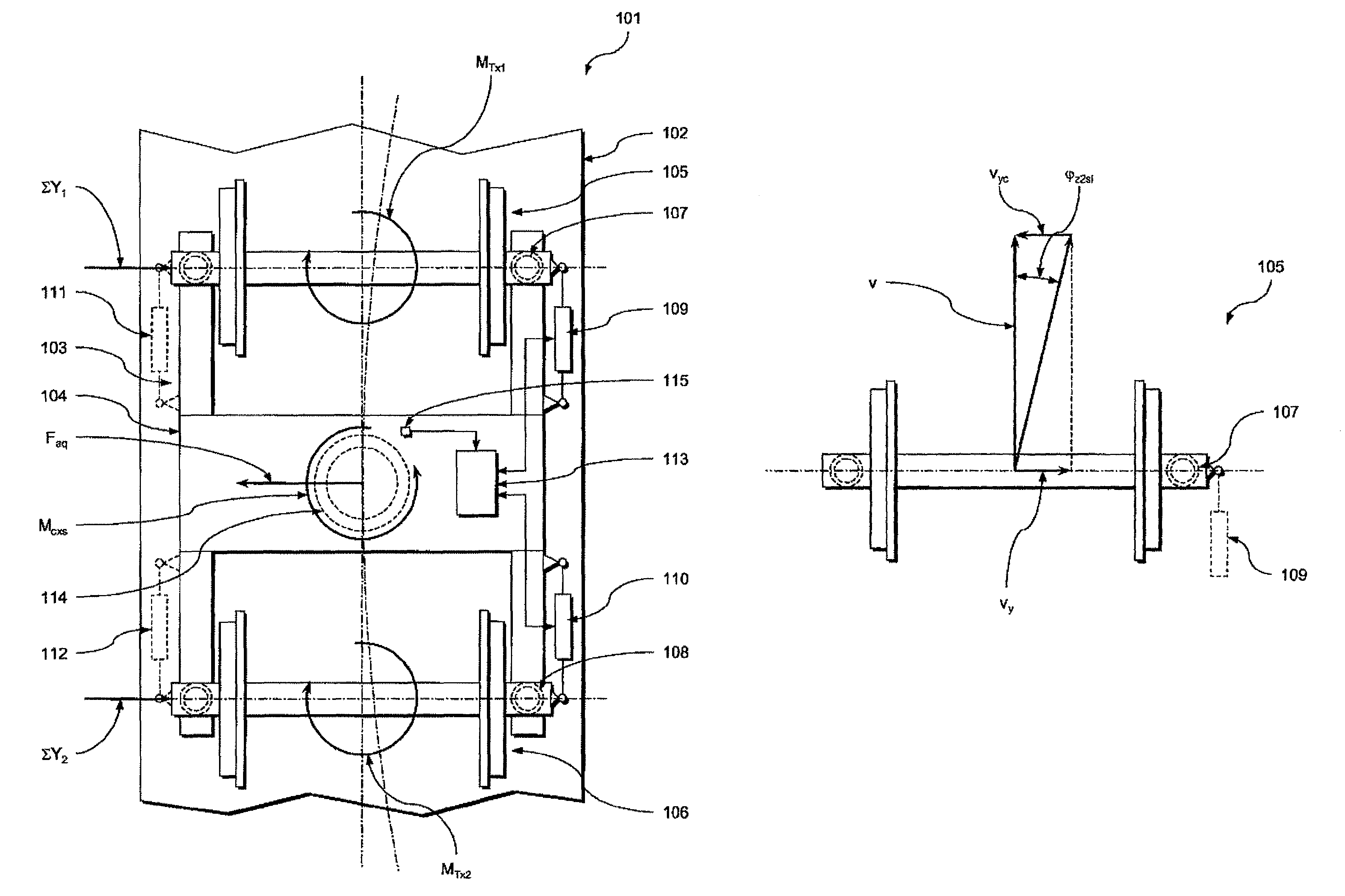
[0084]In a first preferred control variant according to the invention the curve negotiation control, i.e. adjustment of the turning angle of the first wheel set 105 in the first frequency range, is effected through the control unit 113 using a first target turning angle φz1s which corresponds to a first ideal target turning angle φz1si multiplied by a pre-defined first correction factor K1, i.e. the following applies:

φz1s=K1·φz1si.  (11)

[0085]The first ideal target turning angle φz1si is selected such that, upon K1=1, i.e. the first target turning angle φz1s matching the first ideal target turning angle φz1si at the actual curvature of the track, the first wheel set 105 is adjusted curve-radially.

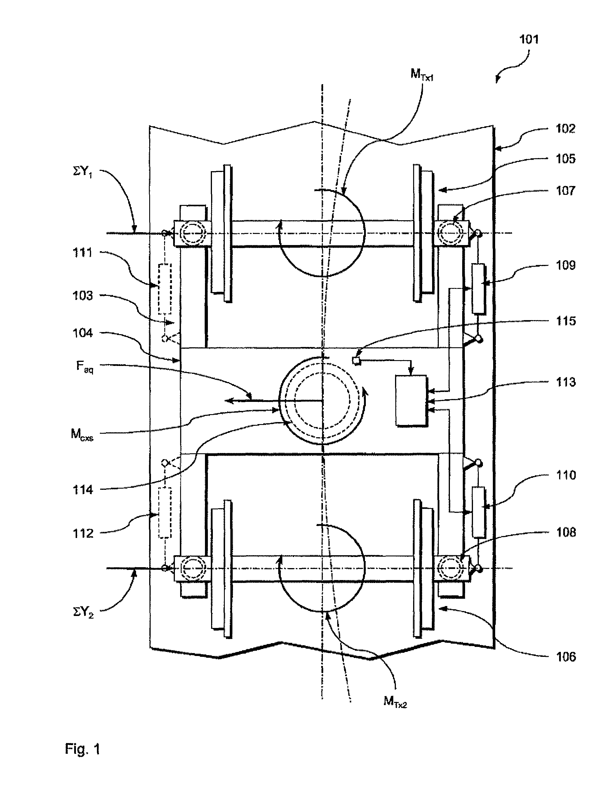
[0086]Furthermore control takes place such that the first actuator 109, in the first frequency range, momentarily essentially does not have to apply any turning moment, i.e. MAkt1=0 applies. As results from the moment balance according to equation (1), with the turning moments at the first ...

second exemplary embodiment

[0109]Thus, with a preferred second control variant, it is provided that although the turning angle of the first wheel set 105 is likewise adjusted in accordance with the above first control variant (i.e. MAkt1=0), the turning angle of the second wheel set 106 is adjusted in the first frequency range using a third target turning angle φz3s which corresponds to a third ideal target turning angle φz3si multiplied by a pre-defined third correction factor K3. The third ideal target turning angle φz3si is selected such that, where K3=1 applies, i.e. if the third target turning angle φz3s matches the third ideal target turning angle φz3si, the turning moment MTX1 on the first wheel set 105 resulting at the actual curvature of the track from the wheel rail pairing is inversely equal to the turning moment MTx2 on the second wheel unit resulting at the actual curvature of the track from the wheel rail pairing (i.e. MTx1=−MTx2).

[0110]From the above equations (3) to (6) the relations shown abo...

third exemplary embodiment

[0116]In a preferred third control variant the curve negotiation control, i.e. the adjustment of the turning angle of the first wheel set 105 in the first frequency range, is effected via the control unit 113 using a first target turning angle φz1s which in turn corresponds to the first ideal target turning angle φz1si multiplied by a pre-defined first correction factor K1, i.e. the following also applies here:

φs1s=K1·φz1si.  (11)

[0117]In this case it is provided that the first actuator 109 is adjusted to follow, in the first frequency range, a turning movement of the first wheel unit caused by a change in the curvature of the track such that the first actuator 109, where K1=1 applies, i.e. where the first target turning angle φz1s matches the first ideal target turning angle θz1si at the actual curvature of the track, in the first frequency range momentarily applies a turning moment MAkt1 which is inversely equal to the turning moment Mcxp1 of the first primary spring mechanism 107...


PUM


Abstract

A method for controlling an active running gear of a rail vehicle including at least one first wheel unit with two wheels, wherein by means of at least one first actuator, which acts between the first wheel unit and a vehicle structure supported thereon by means of a first primary spring mechanism, the turning angle of the first wheel unit about a vertical running gear axis relative to the vehicle structure is adjusted, in a first frequency range, as a function of the actual curvature of the track and/or the turning angle of the first wheel unit about a vertical running gear axis relative to the vehicle structure is adjusted, in a second frequency range, such that transversal movements at least of the first wheel unit, caused by track outlay disturbances or by a sinusoidal course, are counteracted.

Description

BACKGROUND OF THE INVENTION[0001]1. Field of the Invention[0002]The present invention relates to a method for controlling an active running gear of a rail vehicle, and also relates to a device for controlling an active running gear of a rail vehicle as well as to a rail vehicle equipped with a device according to the invention.[0003]2. Description of Related Art[0004]Running gear of rail vehicles are normally subject to a conflict of aims between track stability at high running speeds on straight sections and good curve compliance characteristics on curved sections. Track stability at high running speeds on straight sections requires rigid longitudinal guidance of the wheel units (wheel sets or wheel pairs) while good curve compliance characteristics require curve-radial adjustment of the wheel units and thus soft longitudinal guidance. With respect to known solutions in standard gauge railways, rail vehicles with good curve compliance characteristics therefore usually have a stabil...

Claims


Application Information

Patent Timeline
Patent Type & Authority Patents(United States)
IPC IPC(8): G06F7/00
CPCB61F5/383B61F5/38B61F5/40B61F5/42B61F5/44
Inventor REIMANN, UWELOHMANN, ALFREDDEDE, JANI
Owner BOMBARDIER TRANSPORTATION GMBH
Why Eureka
Try Eureka