
Method and system for heater signature detection diagnostics of a particulate matter sensor
a technology of particulate matter and detection diagnostics, which is applied in the direction of electrical control, instruments, nuclear elements, etc., can solve the problems of difficult to distinguish, difficult to form parts, and air pollution
Patent Information
- Authority / Receiving Office
- US · United States
- Patent Type
- Patents(United States)
- Current Assignee / Owner
- Publication Date
- 2012-08-21
Smart Images
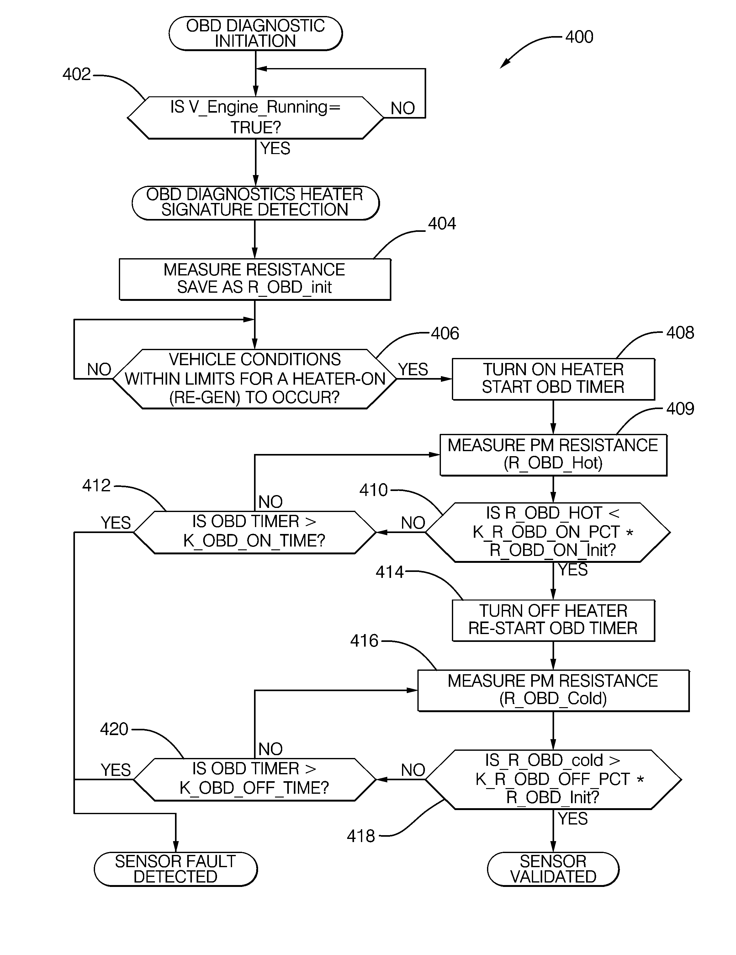
Figure 1 
Figure 2 
Figure 3
Abstract
Description
BACKGROUND OF THE INVENTION
[0001] This invention relates generally to sensors for detecting electrically conductive particulate matter, such as soot, and more particularly to a method and system for diagnosing potential failure modes in such sensors.
[0002] Incomplete combustion of certain heavy hydrocarbon compounds, such as heavy oils, diesel fuel, and the like may lead to particulate formation (e.g., soot). In the operation of internal combustion engines, excessive particulate formation can lead to “smoking” of the engine, which causes air pollution even though the carbon monoxide, hydrocarbons, and other pollutant components of the gaseous state exhaust emissions may be relatively low. Emission regulations require many engines to limit the levels of particulate emissions, and various control technologies such as diesel particulate filters (DPF) have been employed for this purpose.
[0003] In order to monitor the emission of particulate matter in the exhaust streams of certain types of...
Examples
Embodiment Construction
[0021]Referring now to the Figures, where the invention will be described with reference to specific embodiments, without limiting same.
[0022]In describing and claiming algorithms according to the invention, letters and naming conventions are arbitrarily employed to represent numerical values (e.g., ROBD—hot, KR—OBD—on—pct). These naming conventions are used solely to enhance the readability of the description of the invention, and are not intended to have any functional significance whatsoever. The representation of these numerical values is intended to be precisely the same as if, for example completely arbitrary descriptions (e.g., R1, R2, K1, K2) had been used. Additionally, it should be noted that in the practice of the invention, measurements of resistance between the electrodes may be made by applying a known current across the electrodes, measuring the voltage differential between the electrodes, and calculating the resistance using Ohm's law, as is well-known in the art. It...