Growing prosthesis

a prosthesis and growing technology, applied in the field of growing prostheses, can solve problems such as differences in leg length, and achieve the effect of convenient removal of drive or spindle elements, and convenient implanting

Active Publication Date: 2012-08-28
ORTHOFIX SRL
View PDF7 Cites 86 Cited by
  • Summary
  • Abstract
  • Description
  • Claims
  • Application Information

AI Technical Summary

Benefits of technology

[0013]The growing prosthesis therefore has an element with drive that serves for the lengthening of the entire prosthesis and that is able to compensate for postoperative differences in the length of the limbs.
[0035]However, it is also conceivable for the growing prosthesis to be used in adult patients who are being treated as a result of congenital, pathological or accident-related differences in leg length. The compact and scaled-down design of the prosthesis is also easier to implant in such applications, and removal of the drive or of the spindle element can be carried out more easily.

Problems solved by technology

In children and adolescents, however, the natural growth of the bone means that differences in leg length are seen after just a very short period of time and have to be treated medically as a result.

Method used


Image

  • Growing prosthesis
  • Growing prosthesis
  • Growing prosthesis

Examples


Embodiment Construction

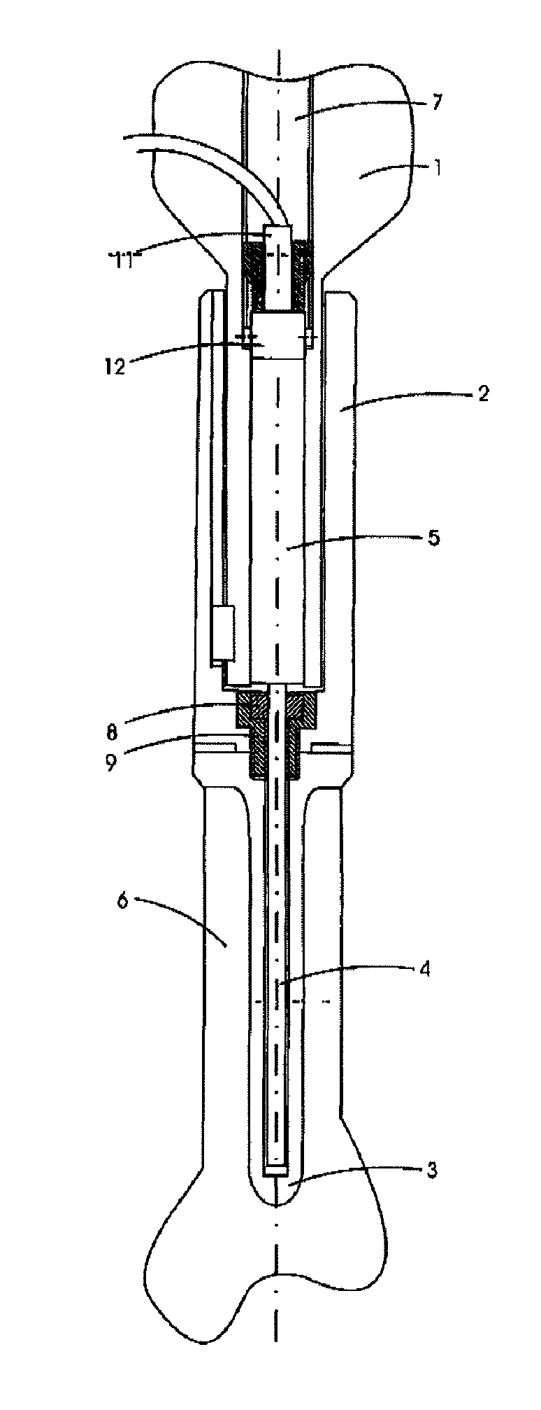
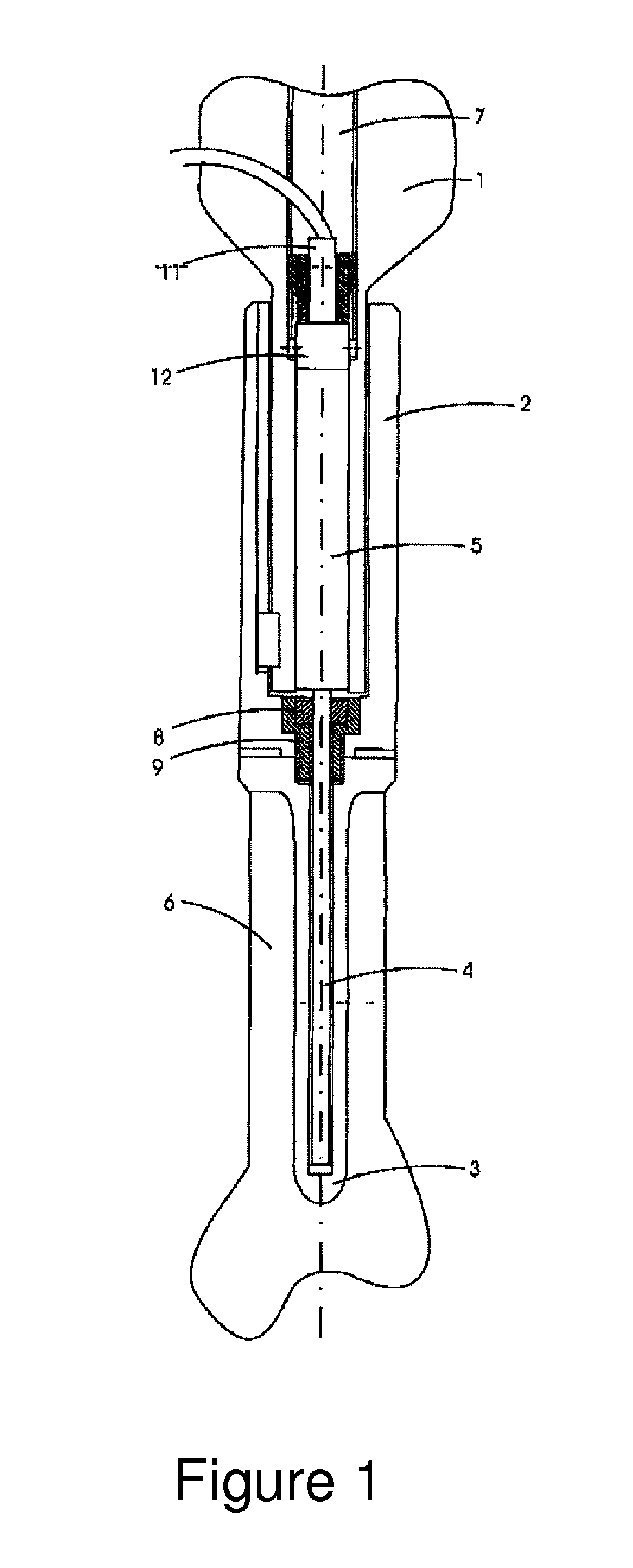
[0040]As is illustrated in FIG. 1, the growing prosthesis is composed of the joint replacement part 1, the prosthesis stem 2, the stem-anchoring element 3, the spindle element 4, and the drive 5 belonging to the spindle element 4.

[0041]The joint replacement part 1 is in this case arranged in the prosthesis stem 2 open at the top.

[0042]The joint replacement part 1 replaces at least some of the removed knee joint or hip joint, is made of implant-grade steel, ceramic or similar materials, and receives the drive 5 of the spindle element 4 in a dedicated bore 7. The sizes of the bore 7 and of the drive 5 are in this case chosen in such a way that there is no significant reduction in the stability of the prosthesis.

[0043]The spindle element 4, in the state of insertion, is located in a bore formed in the stem-anchoring element 3. The spindle element 4 in this case fills a very large part of the length of the stem-anchoring element 3, which is fixed in the bone 6 of the patient. This type ...


PUM


Abstract

A growing prosthesis comprising a joint replacement part, a prosthesis stem, a stem-anchoring element, and an element with corresponding drive provided for the lengthening of the growing prosthesis. The element provided for the lengthening of the growing prosthesis is a spindle element arranged in the stem-anchoring element.

Description

BACKGROUND OF THE INVENTION[0001]The invention relates to a growing prosthesis comprising a bone prosthesis, in particular a joint replacement part, a prosthesis stem, a stem-anchoring element, and an element with corresponding drive provided for the lengthening of the growing prosthesis.[0002]A number of growing prostheses are known from the prior art.[0003]Growing prostheses in most cases consist of a lengthenable prosthesis part and of a stem-anchoring element, which is fixed in the bone. In devices of this kind, an electric drive is located in the prosthesis part. Spindle roller systems are mostly used as the electric drive. A drive unit of this kind is disclosed in EP 0 776 432 B1. The device converts a rotary movement into an axial movement using planetary rollers, which are driven by a drive shaft out of a stationary drive housing and held peripherally at uniform spacings, and a pusher body that can be axially displaced by the planetary rollers.[0004]On account of the movemen...

Claims


Application Information

Patent Timeline
Patent Type & Authority Patents(United States)
IPC IPC(8): A61F2/28A61F2/30
CPCA61F2/3607A61F2002/30087A61F2002/30523A61F2002/30601A61F2002/30604A61F2002/30706A61F2002/482A61F2220/0025A61F2250/0082A61F2/482
Inventor STAUCH, ROMAN
Owner ORTHOFIX SRL
Why Eureka
Try Eureka