
Laminated ceramic electronic component and manufacturing method thereof

a technology of laminated ceramic and electronic components, which is applied in the direction of fixed capacitor details, variable capacitors, fixed capacitors, etc., can solve the problems of reducing the insulation resistance and adverse effects on the reliability of laminated ceramic electronic components, and achieves the improvement of the adhesion strength between the plated film forming the external electrode and the ceramic portion, and prevents moisture from invading. , the effect of improving the moisture load resistance of the laminated ceramic electronic componen

Active Publication Date: 2012-08-28
MURATA MFG CO LTD
View PDF19 Cites 14 Cited by
  • Summary
  • Abstract
  • Description
  • Claims
  • Application Information

AI Technical Summary

Benefits of technology

The present invention provides a laminated ceramic electronic component and a manufacturing method that solve the problems of previous designs. The method involves applying a brazing material containing Ti to a ceramic portion of the component main body, baking the brazing material to form a metal layer, and plating a portion of the external electrode onto the metal layer. A counter diffusion layer is then formed between the metal layer and the plated film to improve adhesion strength and prevent moisture infiltration. The use of a brazing material containing Ag and Cu can further lower the temperature required for baking and increase the joining strength between the ceramic portion and the external electrode. The invention provides a more reliable and efficient solution for manufacturing laminated ceramic electronic components.

Problems solved by technology

In the laminated ceramic capacitor described in JP-A No. 2005-340663, however, moisture tends to invade along an interface between the plated external electrode and the component main body to cause a problem in which the insulating resistance is lowered.
These problems give adverse effects to the reliability of the laminated ceramic electronic component.

Method used


Image

  • Laminated ceramic electronic component and manufacturing method thereof
  • Laminated ceramic electronic component and manufacturing method thereof
  • Laminated ceramic electronic component and manufacturing method thereof

Examples


Embodiment Construction

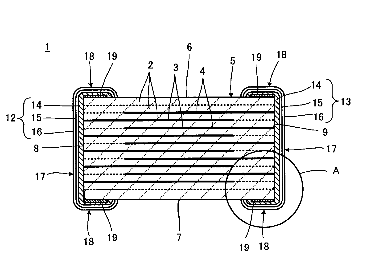
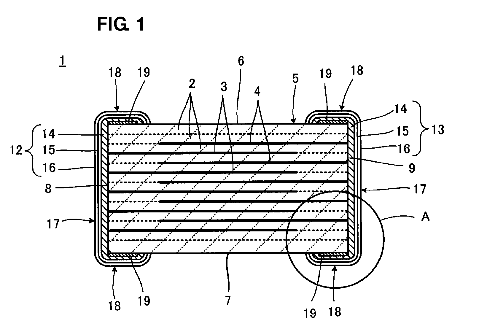
[0031]FIG. 1 is a front view that shows a laminated ceramic electronic component 1 in its cross section in accordance with a preferred embodiment of the present invention. The laminated ceramic electronic component 1, shown in the FIG. 1, forms a laminated ceramic capacitor.

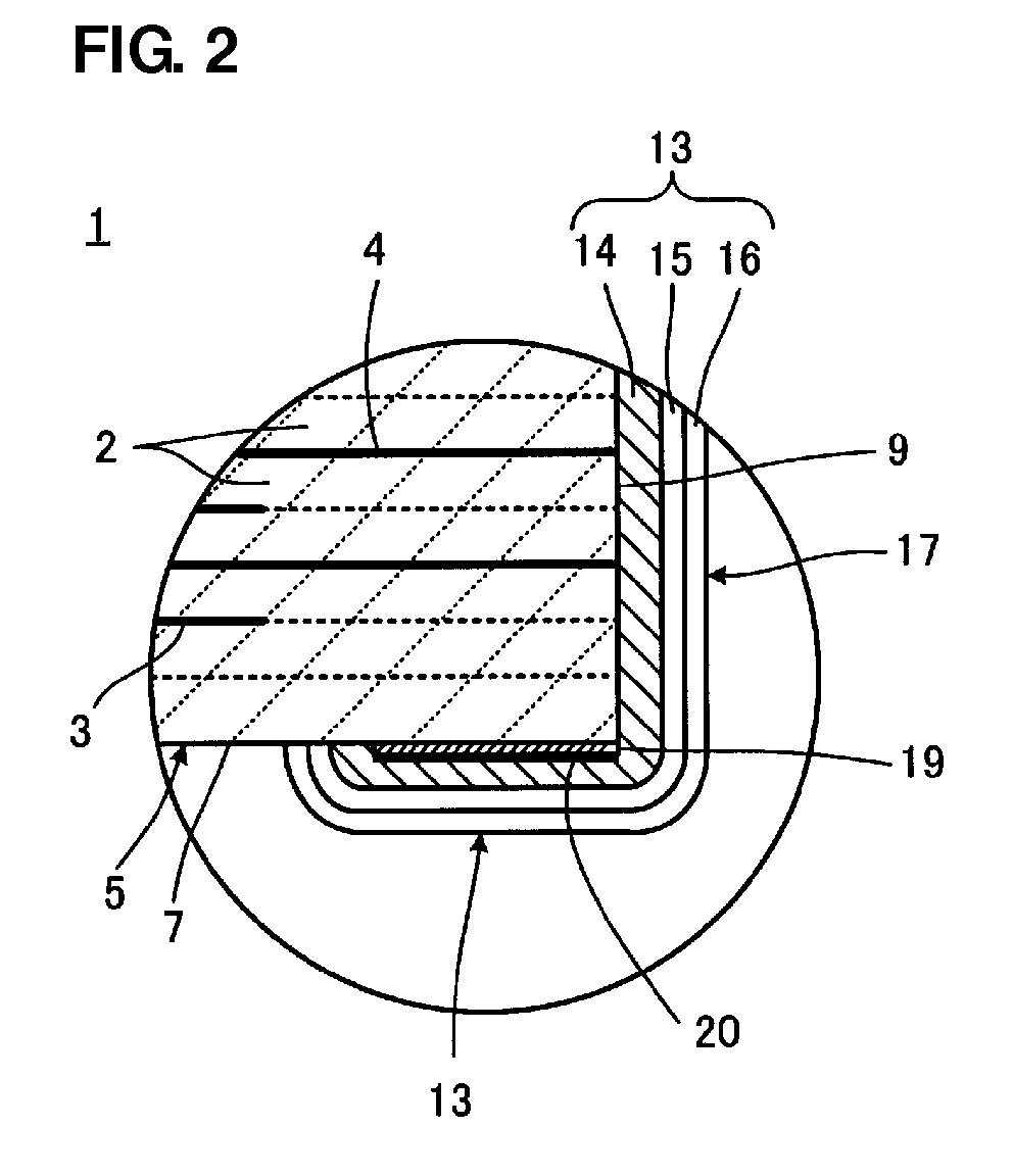
[0032]The laminated ceramic electronic component 1 is provided with a component main body 5 including a plurality of laminated ceramic layers 2 and first and second inner electrodes 3 and 4 that are formed along a specific interface between the ceramic layers 2. The ceramic layer 2 is made from, for example, a barium-titanate-based dielectric ceramic material. The inner electrodes 3 and 4 contain, for example, Ni as a conductive component.

[0033]The component main body 5 preferably has a rectangular parallelepiped shape, for example, and is provided with first and second main surfaces 6 and 7 that are arranged face to face with each other, first and second end surfaces 8 and 9 that couple the first and second main...


PUM

PropertyMeasurementUnit
thicknessaaaaaaaaaa
thicknessaaaaaaaaaa
heightaaaaaaaaaa

Abstract

In a laminated ceramic electronic component in which, by directly carrying out a plating process on an outer surface of a component main body, an external electrode is formed thereon, an attempt is made to improve the adhesion strength between a plated film forming the external electrode and the component main body. A brazing material containing Ti is applied to at least one portion of a surface on which external electrodes of a component main body is formed, and by baking this brazing material, a metal layer containing Ti is formed. Moreover, the external electrodes are formed by a plating process so as to coat at least the metal layer, and a heating process is then carried out so as to cause counter diffusion between the metal layer and the plated film that is to form the external electrodes.

Description

BACKGROUND OF THE INVENTION[0001]1. Field of the Invention[0002]The present invention relates to a laminated ceramic electronic component and its manufacturing method, and more particularly, relates to a laminated ceramic electronic component in which an external electrode is formed on an outer surface of a component main body by directly carrying out a plating process thereon, and a manufacturing method thereof.[0003]2. Description of the Related Art[0004]There have been demands for miniaturizing the size of a laminated ceramic electronic component, such as a laminated ceramic capacitor. For example, in the laminated ceramic capacitor, when the component main body is miniaturized in an attempt to satisfy the demands for small size, in general, its electrostatic capacity becomes smaller. Therefore, it is proposed to make the volume of the electrode smaller as a measure that can satisfy the demands for small size.[0005]Conventionally, the external electrode generally has a layer stru...

Claims


Application Information

Patent Timeline
Patent Type & Authority Patents(United States)
IPC IPC(8): H01G4/00
CPCH01G4/2325H01G4/30
Inventor NISHIHARA, SEIICHIMATSUMOTO, SHUJIMOTOKI, AKIHIROOGAWA, MAKOTO
Owner MURATA MFG CO LTD
Learn More