High-density fixture vise

a fixture and high-density technology, applied in the field of vises, can solve the problems of limiting the depth of contouring, intricate design of jaws, and not having the functionality for use with other workpieces

Inactive Publication Date: 2012-09-04
HIRSH PRECISION PROD INC
View PDF82 Cites 11 Cited by
  • Summary
  • Abstract
  • Description
  • Claims
  • Application Information

AI Technical Summary

Benefits of technology

[0007]Provided herein are multi-station machine vises that may utilize soft jaws, which in one aspect are symmetrical and machineable on all four sides. The jaws being identical in size and configuration makes them interchangeable / usable on any vise station, which results in reduced operating costs. In a further aspect, the movable jaws are precisely located and fastened to the vise utilizing a jaw carrier, which incorporates a pull-down action to eliminate jaw lift. The jaw carrier includes a downwardly positioned wedge design that engages a corresponding wedge on a slide that moves the jaw carrier and the jaw. Incorporating the pull-down mechanism into the jaw carrier disposed between the slide and the jaw allows for simplifying the design and manufacture of the jaws.
[0008]According to a first aspect of the invention, a machine vise is provided that allows for substantially eliminating jaw lift caused by tightening a movable jaw relative to a stationary jaw while an element is compressed between these jaws. Typically, the vise includes a base having recess that defines the longitudinal axis. The bottom surface of the base also defines a reference plane. A stationary jaw is removably mounted to the base. The stationary jaw is typically mounted relative to a top surface of the base above the recess. A first slide is disposed in the recess for selective movement along the longitudinal axis. A drive screw or other actuator may effect movement of the first slide. The slide is utilized to move a jaw to and away from the stationary jaw. More specifically, the slide includes a body and a slide carrier head that extends above the body. In this particular arrangement, the slide carrier head includes an undercut lip. A jaw carrier is also provided as a recess in its lower surface that is sized to receive the slide carrier head. This recess includes an overcut lip for complimentary engagement with the undercut lip of the slide carrier head. This first jaw carrier also includes an upper surface having an outside peripheral edge. A first jaw of the vise has a recess in its bottom surface that is sized to conformably receive the outside peripheral edge of an upper surface of the first jaw carrier. The complimentary engagement of the overcut lip with the undercut lip, which is sometimes defined as wedge surfaces, provides a pull-down effect between the slide and the jaw carrier as the vise is tightened. The conformal fit of the jaw carrier into the recess in the bottom surface of the first jaw transfers the pull-down effect from the jaw carrier to the jaw without the jaw requiring an undercut recess in its bottom surface.
[0010]Due to the simplified nature of the recess in the bottom of the jaw, the jaws are very easy to manufacture. That is, unlike a jaw having an undercut recess in its bottom surface that requires more complex milling, the substantially perpendicular edge surfaces of the recess permit the jaws of the present aspect to be readily machined. This allows most machine shops to readily and efficiently produce their own replacement jaws for the vise. That is, unlike soft jaws that utilize specialized undercut recesses to provide pull-down effect, here the pull-down effect is provided between two parts of the vise. Specifically, the pull-down effect is provided between the slide and the intermediate jaw carrier. Accordingly, the slide and the jaw carrier may be made of very durable materials such as, for example, stainless steels. This permits the soft jaws to be produced of much softer materials such as aluminums and mild steels.
[0012]In one arrangement, the vise is a multiple station vise where first and second movable jaws move relative to the stationary jaw. These jaws may be disposed on opposing sides of the stationary jaw and may operate together to clamp one or more work pieces between the respective movable jaw and the stationary jaw. In such an arrangement, a second slide is disposed in the recess that engages a second jaw carrier that is received within a recess in the bottom of the second jaw. The second slide may include a head having an overcut lip that is received within a recess in the second jaw carrier having a complimentary undercut lip to provide pull-down effect for the second jaw.
[0017]The selective movement of one of the jaws in relation to the other provides what may be termed as a “third hand.” That is, a user may selectively open one of the jaws prior to opening the other jaw to facilitate removal and / or engagement of elements within the machining vise.
[0019]In a further arrangement, the use of the drive screw which passes through one of the slides without threaded engagement allows for fixing the position of the slide having the threaded aperture to transform the multi-station vise into a single station vise. For instance, in one arrangement a threaded element (e.g., bolt or screw) may extend through a second end of the vise and engage the slide that is in threaded engagement with the drive screw. Accordingly, this slide may be affixed relative to the base such that the subsequent turning of the drive screw only moves the slide with the non-threaded aperture.

Problems solved by technology

In this regard, after a soft jaw is milled for a particular workpiece, the jaw may not have functionality for use with other workpieces.
One complicating factor for maintaining such strict tolerances of the workpieces is a tendency for a movable jaw to lift as the jaw compresses a workpiece relative to the stationary jaw.
Such ‘jaw-lift’ may result in, for example, a workpiece being slightly out of position relative to a known coordinate location of a CNC milling machine.
However, the design of such prior art machining vises that provide such a pull-down force often require intricately designed jaws having specialized recessed lower surfaces.
In addition, such specialized jaws often have a high profile, or in some instances, a relatively thin layer of metal over the recess, which restricts the depth of contouring that can be done for holding workpiece on the top of the movable jaw.

Method used


Image

  • High-density fixture vise
  • High-density fixture vise
  • High-density fixture vise

Examples


Embodiment Construction

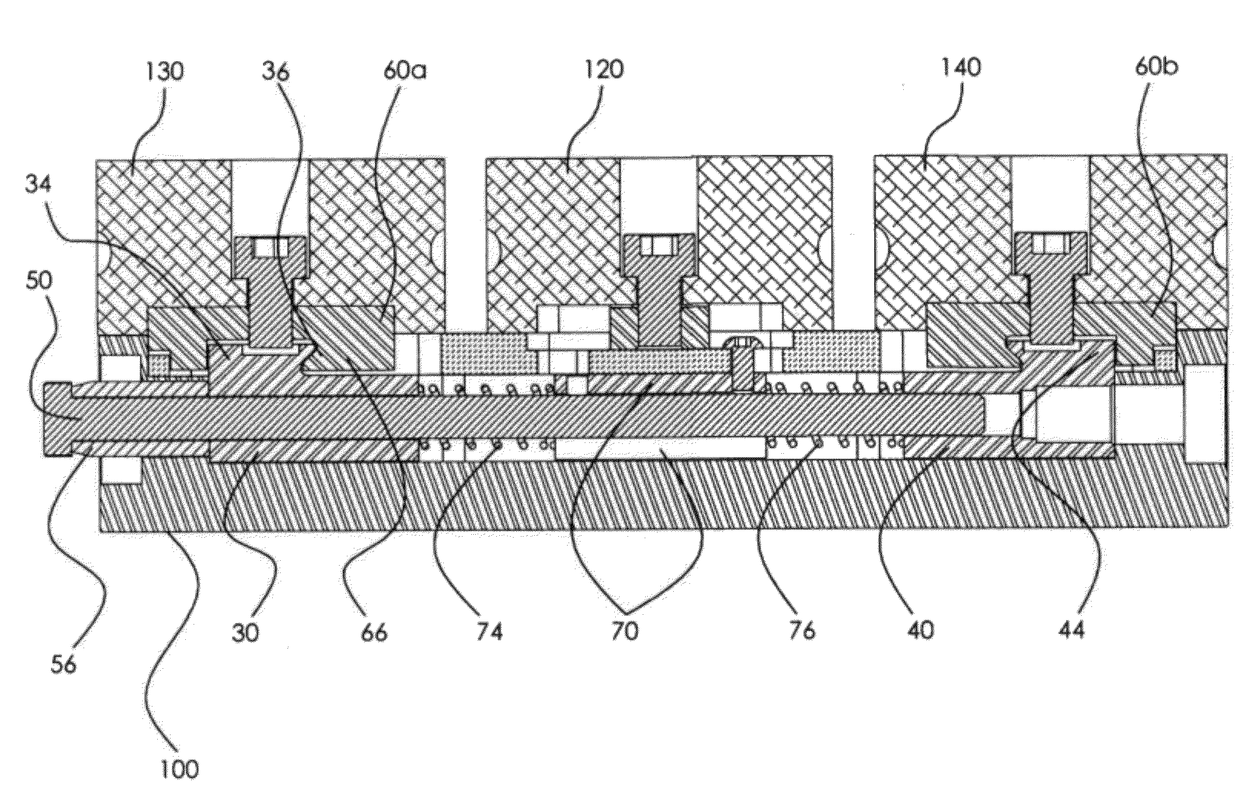
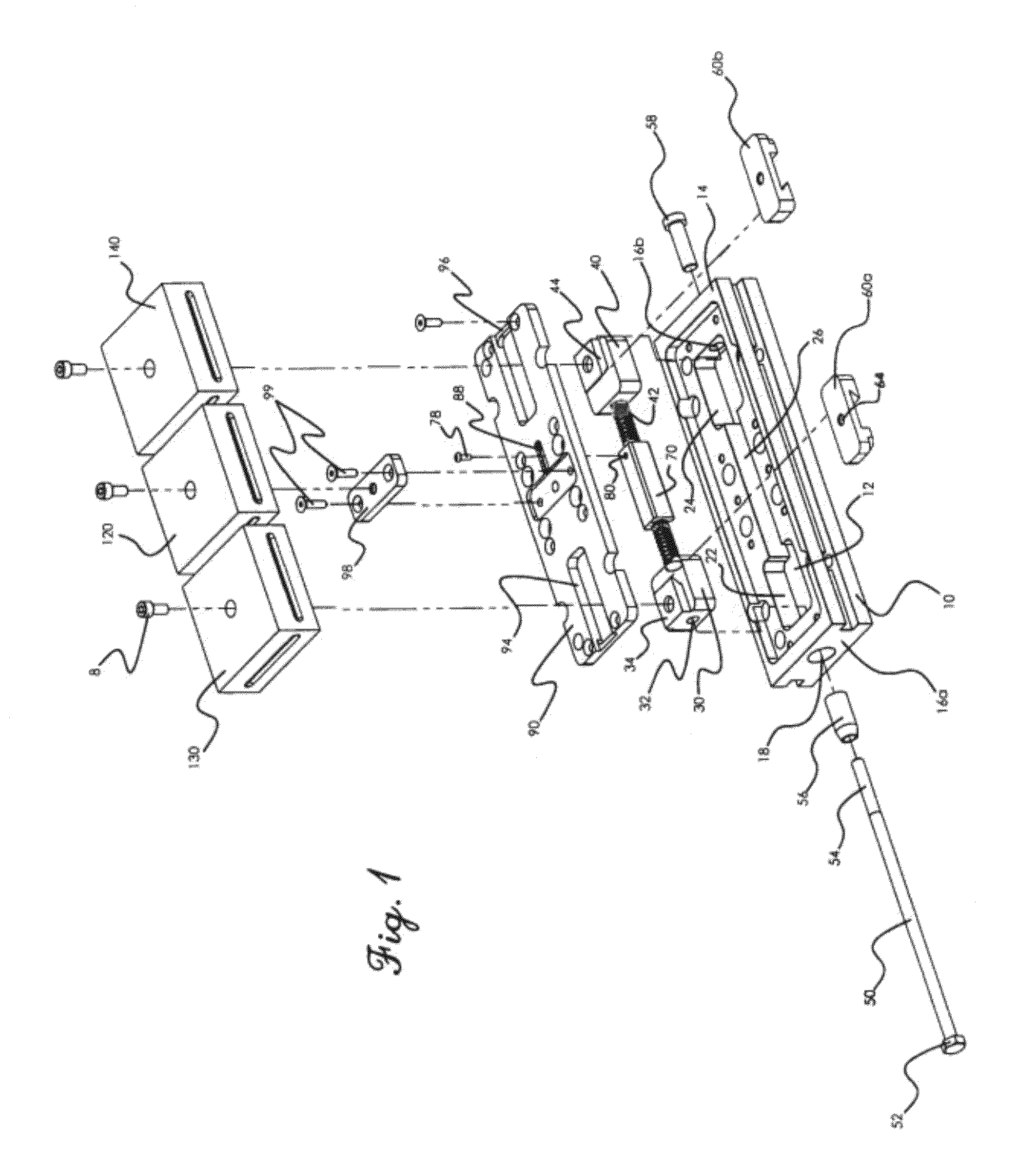
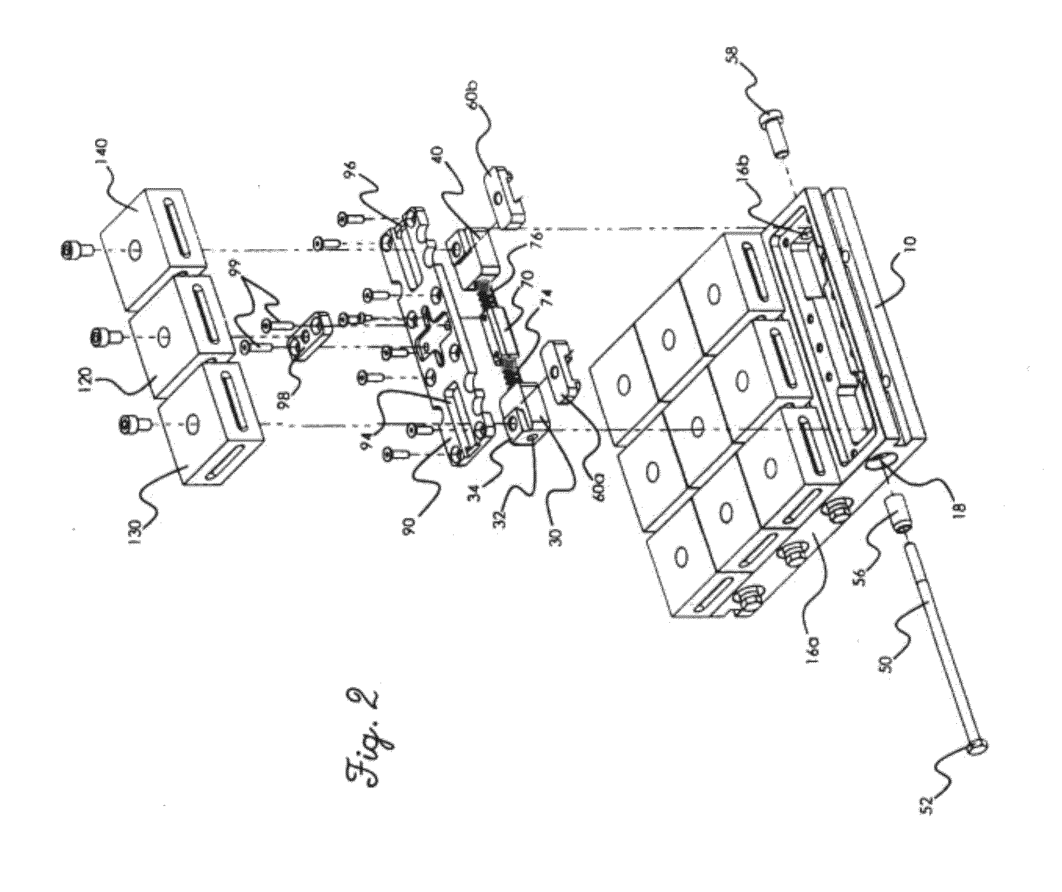
[0029]FIGS. 1 and 2 illustrate perspective exploded views of a dual-station machine vise and a multi-station machine vise, respectively. It will be appreciated that the multi-station machine vise of FIG. 2 effectively comprises four of the dual-station vises illustrated in FIG. 1 mounted in parallel. However, the operative components of the internal drive assemblies of both of these devices are substantially identical. For purposes of discussion, the dual-station vise of FIG. 1 is discussed, however, it will be appreciated that the discussion of the components of this dual-station vise are applicable to the multi station vise of FIG. 2.

[0030]As shown, the vise 100 has first and second movable jaws 130 and 140 that may be utilized to compress work pieces relative to a stationary central jaw 120. As shown, the base 10 includes a drive assembly recess 12 that extends from near a front wall or end 16a of the base 10 to the near rear wall or end 16b of the base 10. Of note, the drive ass...


PUM


Abstract

A multi-station machine vise that is disclosed herein that utilizes soft jaws, which are symmetrical and machineable on all four sides. The jaws being identical in size and configuration makes them interchangeable / usable on any vise station, which results in reduced operating costs. The movable jaws are precisely located and fastened to the vise utilizing a jaw carrier, which incorporates a pull-down action to eliminate jaw lift. The jaw carrier includes a downwardly positioned wedge design that engages a corresponding wedge on a slide that moves the jaw carrier and the jaw. Incorporating the pull-down mechanism into the jaw carrier disposed between and slide and the jaw allows for simplifying the design and manufacture of the jaws.

Description

FIELD OF INVENTION[0001]The invention relates to a vise used in precision machining processes. More specifically, the invention is directed to a multi-station machine vise that reduces or eliminates jaw lift without requiring intricately designed jaws.BACKGROUND OF THE INVENTION[0002]Multi-station (e.g., dual-station) precision machining vises are known in the art. Typically, such multi-station machining vises include first and second movable jaws that are disposed on opposing sides of a stationary jaw. A drive mechanism advances each of the movable jaws to and / or away from the stationary jaw to clamp workpieces within the vise.[0003]Often, it is desirable to hold irregular shaped workpieces within such a vise. Accordingly, many precision machining vises now utilized what may be termed ‘soft jaws’ which are adapted to that may be milled to conform to the surface of the workpiece that they are to hold. In this regard, after a soft jaw is milled for a particular workpiece, the jaw may...

Claims


Application Information

Patent Timeline
Patent Type & Authority Patents(United States)
IPC IPC(8): B25B1/20
CPCB25B1/103B25B1/2473B25B1/2478B25B1/2484B25B1/2489
Inventor TEO, RENE
Owner HIRSH PRECISION PROD INC
Why Eureka
Try Eureka