Prosthetic tissue valve

a tissue valve and valve body technology, applied in the field of prosthetic tissue valves, can solve the problems of valve tissue wear, mechanical valves also risk developing stenosis at the valve replacement site, and incurring chronic hemolysis, so as to maximize the luminal space

Active Publication Date: 2012-09-04
CORMATRIX CARDIOVASCULAR INC
View PDF175 Cites 25 Cited by
  • Summary
  • Abstract
  • Description
  • Claims
  • Application Information

AI Technical Summary

Benefits of technology

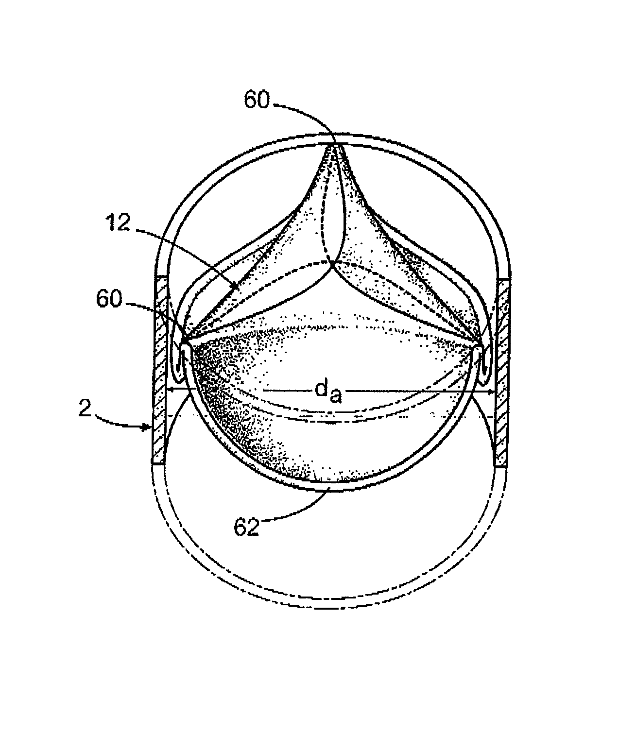
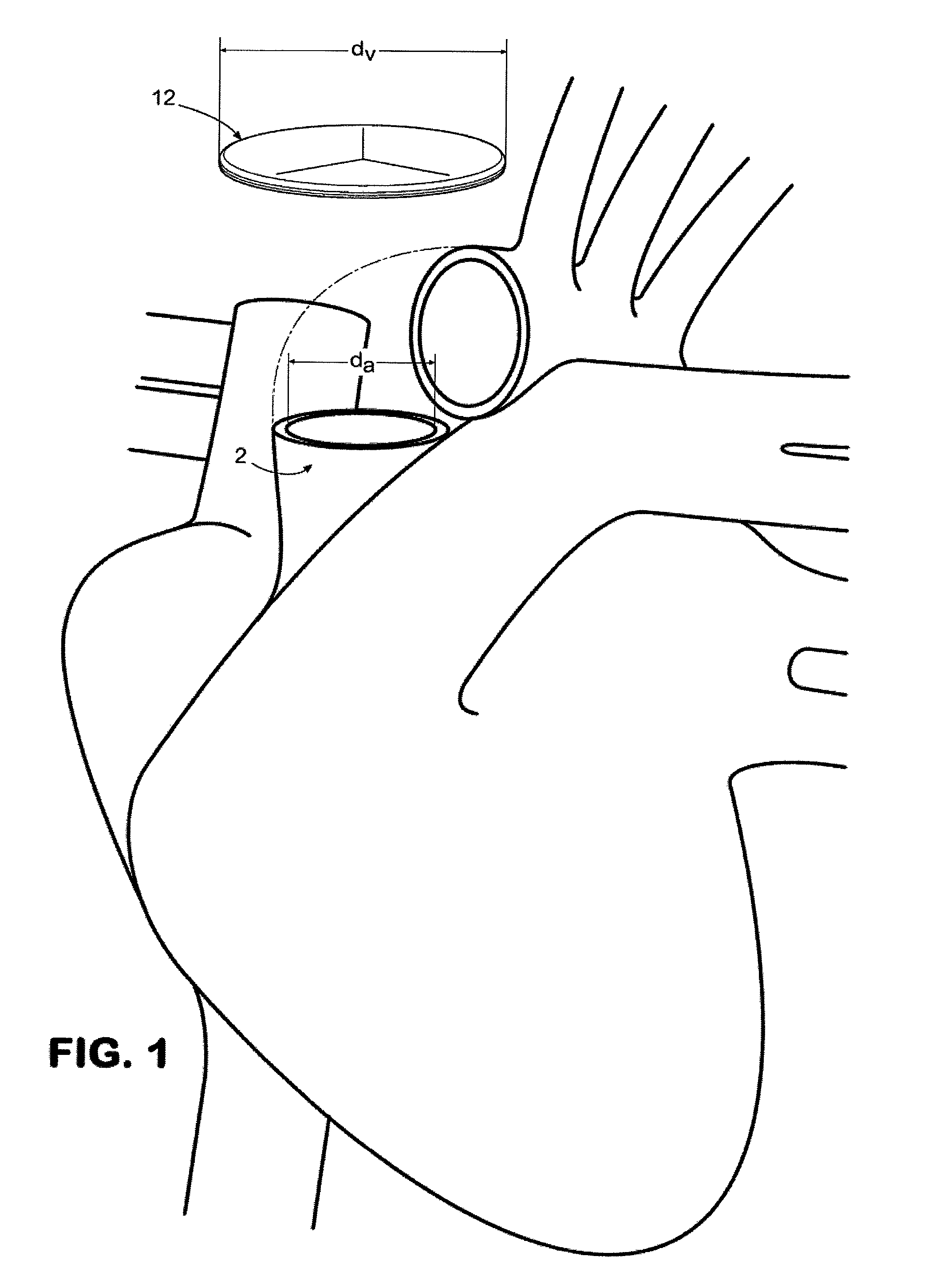
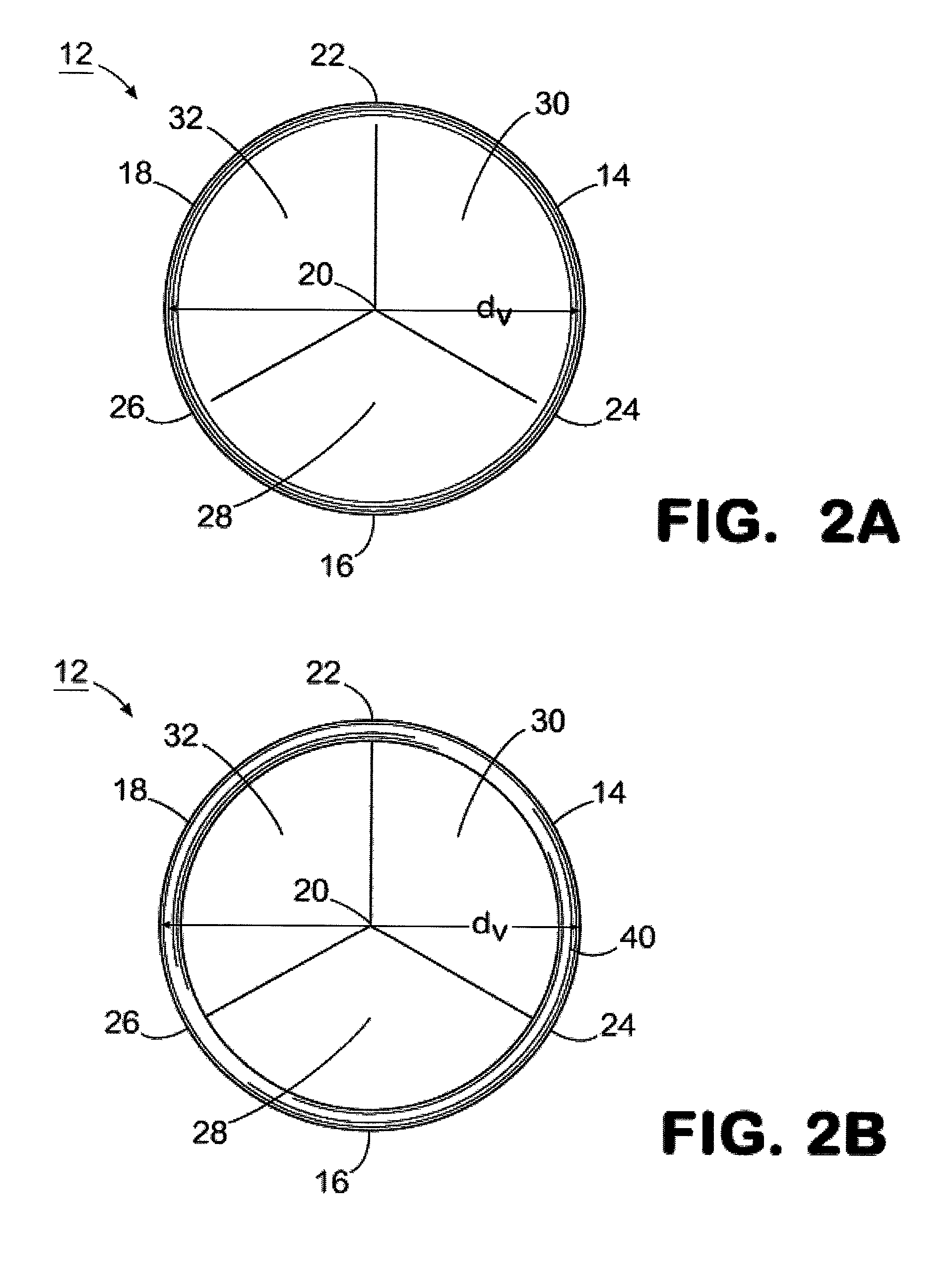
[0014]In one aspect, a valve disclosed herein is designed to replace a native valve such as the aortic, pulmonary, mitral, or tricuspid valves in the heart of a subject. In one aspect, the valve can have a plurality of leaflets that extend generally inwardly relative to a valve circumference toward a radial center point of the valve such that at least a portion of each leaflet contacts its adjacent leaflets. When placed on a flat surface in an unstressed position before attachment of the valve in the subject, the valve is substantially flat or planar and can therefore, in a further aspect, be formed from a substantially planer material. In one aspect, the valve can have a sewing ring to which the leaflets are attached and the sewing ring can be attached to the valvular annulus at the site of valve replacement. In various aspects, it is contemplated that the sewing ring can be less than about 5 mm wide, and more preferably less than about 1 mm wide, thereby maximizing the portion of the luminal space that is available for blood flow.
[0016]Although theoretically any extracellular matrix material can be used for this purpose, preferred extracellular matrix materials are exogenous mammalian extracellular matrices, such as those derived from porcine or bovine sources. In one aspect, the extracellular matrices can be derived from such tissues as small intestine submucosa (SIS), stomach submucosa (SS), liver basement membrane (LBM), urinary bladder submucosa (UBS), and in general any other sources of extracellular matrix material that are retrievable from a mammal. The advantage of using the extracellular matrix materials from mammalian sources is that these materials are known to regenerate tissue at the site where they are placed in a human or other mammal. In use, the extracellular matrix material of the sewing ring and the valve can be in communication with the circulation of a subject and can develop into human tissue after about 3 to 6 months in the subject's body. Thus, the regenerated tissue will be like new tissue with the coordinate lifespan of new tissue, and will not need to be replaced. In addition, with pediatric patients, the leaflet tissue can grow with the patient and expand as the patient's heart tissue grows to adult proportions, thus eliminating the risk of needing a second or subsequent surgery to replace the valve or the sewing ring.
[0019]Preferred attachment means include using multiple sutures along the sewing ring, forming attachment of the sewing ring in an up and down configuration along the annular region to generally position the sewing ring at the location of the annulus of the defective valve, and directing three-dimensional structural formation of the leaflets, which structure directs the leaflets to function similarly to the function of native leaflets in healthy native valves.

Problems solved by technology

Mechanical valves also risk development of stenosis at the valve replacement site, and incur chronic hemolysis (damage to red blood cells by the mechanical action of the valve).
They fail because the tissue of the valve begins to wear, at least in part because the valves are retrieved after already having undergone partial lifetimes of use.
Tissue valves in younger people wear out more quickly due to the more active blood flow in younger people, which causes rapid calcification and places great mechanical demands on the valves.
However, pediatric valve replacements are particularly challenging because the patients frequently outgrow the implanted mechanical valve and require surgical intervention to replace the pediatric valve with a larger valve.
Progressive deterioration of a tissue valve can lead to stenosis, which manifests itself as an obstruction of forward flow through the valve when the valve is in its open position.
More commonly, deterioration of a valve produces tears in the valve leaflets that cause regurgitation, which manifests itself as a leakage in the valve when the valve is in its closed position.
In addition, attachment of known synthetic valves is accomplished using a ring that remains in a single plane following implantation, thereby risking perivalvular leakage in the same manner as the attachments of mechanical valves.
The time and spatial constraints imposed by surgery, however, often dictate that the shape of the resulting annulus is less than perfect for attachment of a sewing ring.
The implantation of a prosthetic heart valve, including mechanical valves and bioprosthetic valves (i.e., “tissue” valve), requires a great deal of skill and concentration given the delicate nature of the native heart tissue, the spatial constraints of the surgical field and the criticality of achieving a secure and reliable implantation.
Due to the inability of conventional sewing rings to easily stretch, if the selected size of the sewing ring is even slightly too small, attachment can only be achieved by placing undue tension on the tissue and sutures.
Unfortunately, standard sizing tools are provided in increments based on an overall opening size, and may not be able to accurately measure a less than optimally formed annulus.

Method used


Image

  • Prosthetic tissue valve
  • Prosthetic tissue valve
  • Prosthetic tissue valve

Examples


Embodiment Construction

[0030]The present invention may be understood more readily by reference to the following detailed description, examples, drawings, and claims, and their previous and following description. However, before the present devices, systems, and / or methods are disclosed and described, it is to be understood that this invention is not limited to the specific devices, systems, and / or methods disclosed unless otherwise specified, as such can, of course, vary. It is also to be understood that the terminology used herein is for the purpose of describing particular aspects only and is not intended to be limiting.

[0031]As used in the specification and the appended claims, the singular forms “a,”“an” and “the” include plural referents unless the context clearly dictates otherwise. Thus, for example, reference to a “leaflet” can include two or more such leaflets unless the context indicates otherwise.

[0032]Ranges may be expressed herein as from “about” one particular value, and / or to “about” anothe...


PUM


Abstract

A prosthetic tissue valve for aortic, pulmonary, mitral or tricuspid valve replacement is described herein. A sewing ring for use with the prosthetic tissue valve is also described. The valve can have a circumference that is a predetermined distance larger than the circumference of an annulus in a defective valve. The valve can be substantially planar in an unstressed position before attachment at the annulus and substantially non-planar upon attachment in a biased position at the annulus. Methods are provided for placing the valve as described herein in the biased position within the annulus of the defective valve.

Description

CROSS-REFERENCE TO RELATED APPLICATIONS[0001]This application is a continuation-in-part of co-pending U.S. patent application Ser. No. 11 / 958,405, filed Dec. 18, 2007, and U.S. patent application Ser. No. 11 / 958,407, filed Dec. 18, 2007, both of which are hereby incorporated by reference in their entireties. This application also claims the benefit of the filing date of U.S. Provisional Patent Application Ser. No. 61 / 295,503, filed Jan. 15, 2010, which is hereby incorporated by reference in its entirety.FIELD OF THE INVENTION[0002]The invention generally relates to a prosthetic tissue valve for replacing defective aortic, pulmonary, mitral or tricuspid valves. More specifically, the invention relates to a prosthetic tissue valve that is substantially planar prior to implantation in an annulus and substantially non-planar following implantation in an annulus.BACKGROUND OF THE INVENTION[0003]In general, two types of artificial heart valves are used to replace defective heart valves: m...

Claims


Application Information

Patent Timeline
Patent Type & Authority Patents(United States)
IPC IPC(8): A61F2/24
CPCA61F2/2412A61M39/22
Inventor MATHENY, ROBERT G.
Owner CORMATRIX CARDIOVASCULAR INC
Why Eureka
Try Eureka