Standby restoration signaling for optical networks

a technology of standby restoration and optical network, applied in the field of network communication, can solve the problems of limiting the maximum bandwidth of the signal, oeo switching is also expensive, and the transparent oxc architecture does not allow easy optical signal quality monitoring

Active Publication Date: 2012-09-04
AT&T INTPROP I LP
View PDF4 Cites 11 Cited by
  • Summary
  • Abstract
  • Description
  • Claims
  • Application Information

AI Technical Summary

Problems solved by technology

OXCs based on OEO switching limit the maximum bandwidth of the signal due to their electronic circuits.
OEO switching is also expensive due to the number of optical transponders.
Because the signals are kept in the optical format, the transparent OXC architecture does not allow easy optical signal quality monitoring.
However, opaque OXCs and interfaces are more expensive.
In contrast, in a transparent optical network, an optical signal service connection is not terminated at each hop along its path, meaning that each link OXC does not provide wavelength conversion.
Since the OEO regenerators are expensive devices, first generation ULH networks were not inexpensive.
They also complicate dynamic reconfiguration and restoration in the optical network.
However, in a transparent optical network, the OXC itself does not have wavelength conversion capability and opaque optical network shared mesh restoration schemes cannot be applied to transparent optical networks directly.
However, they are not dedicated to a specific restoration path prior to a failure.
The challenge in reliable optical network design is to provide fast restoration in conjunction with restoration capacity in a cost effective manner.

Method used


Image

  • Standby restoration signaling for optical networks
  • Standby restoration signaling for optical networks
  • Standby restoration signaling for optical networks

Examples


first embodiment

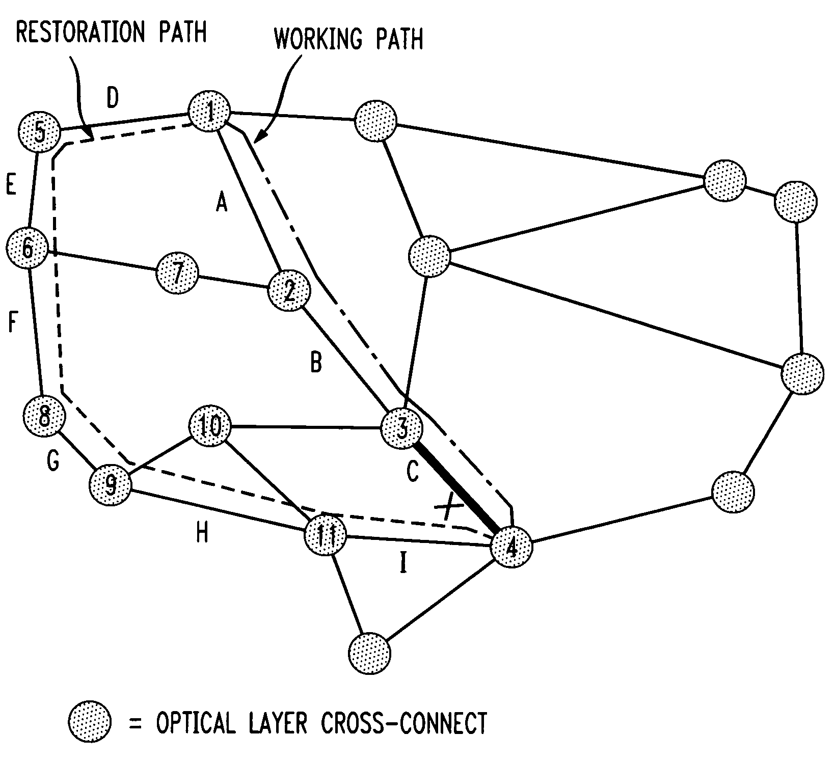
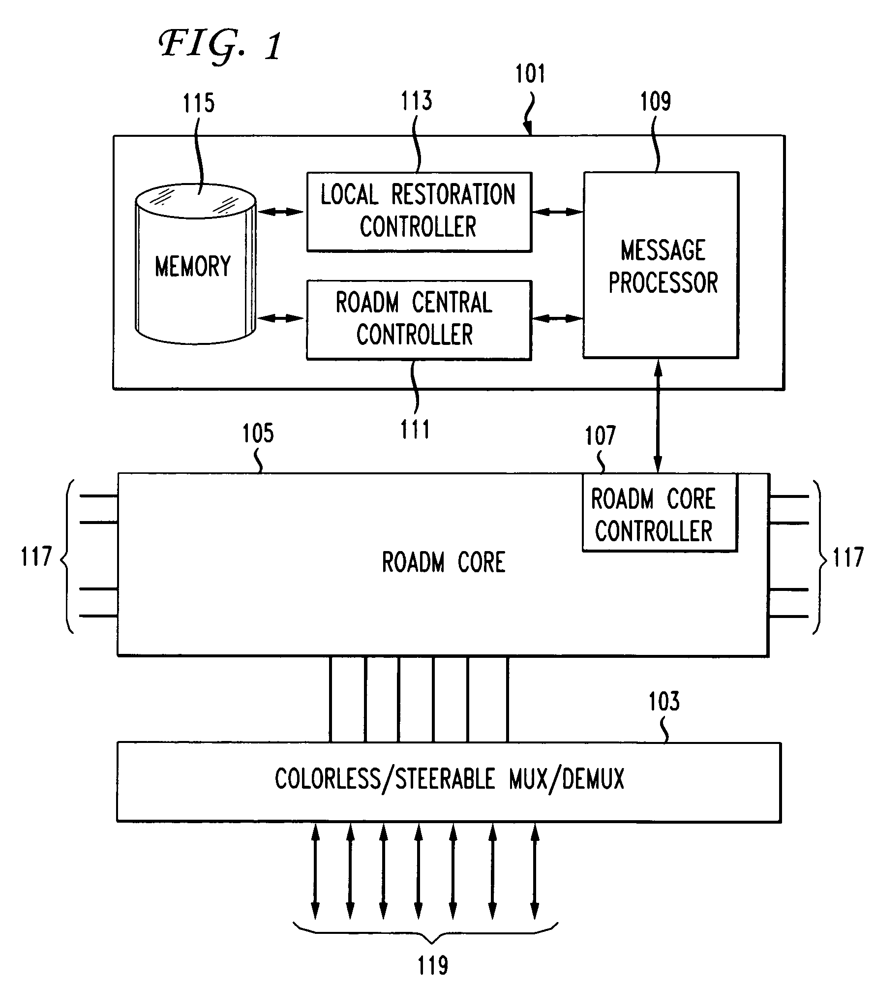
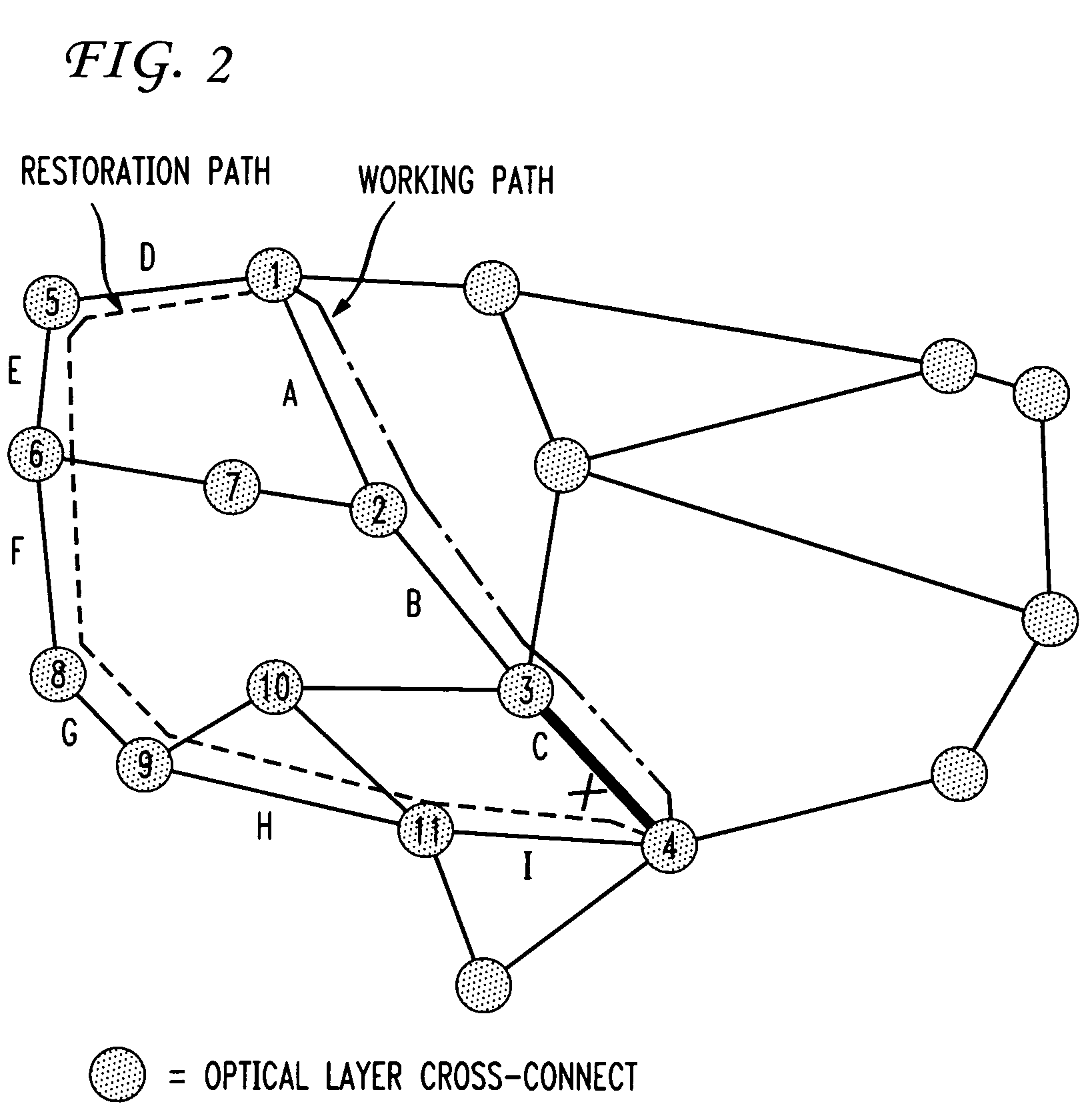
[0054]The first embodiment is one-ended restoration path signaling (step 3009). This embodiment chooses either the ingress or egress end OXC 101 (OXC 1 or OXC 4) of a service path as a control OXC 101. For example, OXC 1 is the control OXC in FIG. 2. If the service path experiences a fiber cut or an inter-OXC failure, the control OXC, OXC 1, will detect the failure via a loss of light or a loss of frame. If the failure is a one-way failure from OXC 1 to OXC 4, only the receiving end OXC, OXC 4, of the failure can detect the failure. If the receiving end OXC is the control OXC, it will initiate the restoration method, otherwise, a Far End Receive Failure (FERF) alarm or other mechanism where the end OXC that detects the “receive” signal failure issues an alarm to the path other end OXC over Synchronous Optical Network (SONET) overhead or other protocol of the constituent connection signal to trigger restoration. If OXC 4 is not the control OXC, OXC 4 would send a FERF alarm to OXC 1,...

second embodiment

[0071]The second embodiment is two-ended restoration path signaling. In two-ended signaling, both an ingress OXC and an egress OXC initiate restoration independently upon detection of a signal failure alarm. Two restoration messages are initiated and forwarded towards each other and intersect between, or at either the ingress or egress OXC.

[0072]Two-ended signaling may complete restoration faster than one-ended signaling, but extra processing protocol is required over that required for one-ended signaling. The added protocol resolves contention in wavelength channel selection for the OXC where the two restoration processes intersect.

[0073]For two-ended signaling, when link C fails, both OXC 1 and OXC 4 detect a loss of light or a loss of frame, and initiate the restoration method on the restoration path. When the two restoration messages meet at some location on the restoration path, wavelength channel contention is resolved between the two ends of the restoration standby.

[0074]To r...


PUM


Abstract

Systems and methods are described that provide a distributed restoration signaling protocol for shared mesh restoration with standbys for transparent optical networks.

Description

CROSS REFERENCE TO RELATED APPLICATIONS[0001]This application claims the benefit of U.S. Provisional Application No. 61 / 191,829, filed on Sep. 12, 2008, the disclosure which is incorporated herein by reference in its entirety.BACKGROUND OF THE INVENTION[0002]The invention relates generally to network communications. More specifically, the invention relates to systems and methods that provide a distributed restoration signaling protocol for mesh optical networks, including opaque, transparent, and translucent Optical cross-Connects (OXCs).[0003]An OXC is used to switch high-speed optical signals in a fiber optic network. There are several implementations of OXCs. One is implemented in the electronic domain. All the input optical signals are converted into electronic signals using optical transponders after they are demultiplexed. The electronic signals are then switched by an electronic switch module. Finally, the switched electronic signals are converted back into optical signals us...

Claims


Application Information

Patent Timeline
Patent Type & Authority Patents(United States)
IPC IPC(8): H04J1/16H04J3/14H04J14/00
CPCH04J14/0284H04J14/0246H04J14/0269H04J14/0268H04J14/0212H04J14/0258H04J14/0257
Inventor LI, GUANGZHICHIU, ANGELA LANDOVERSPIKE, ROBERT DUNCANSTRAND, JOHN L.
Owner AT&T INTPROP I LP
Why Eureka
Try Eureka