[0011]It is clear that the possibility to bring the floor panels, by means of the positioning means, more particularly by means of the positioning portions, into an initially coupled position in which they can move away from each other as well as towards each other, provides for that a floor covering composed of such floor panels can beneficially counterbalance both expansion and shrinkage of the floor panels to a certain extent.
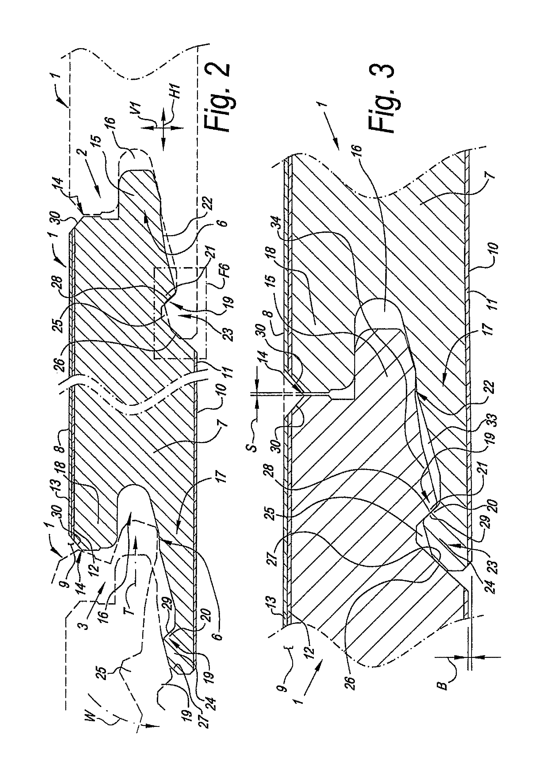
[0022]The inventors have found that the bending ability of at least one of the lips, preferably the
lower lip, bordering the groove may be applied for providing a
restoring force towards an initial position. According to various forms of embodiment of the present invention, this finding may lead to an efficient and / or effective
absorbance of forces resulting from shrinkage or expansion of the floor panels in a floor covering.
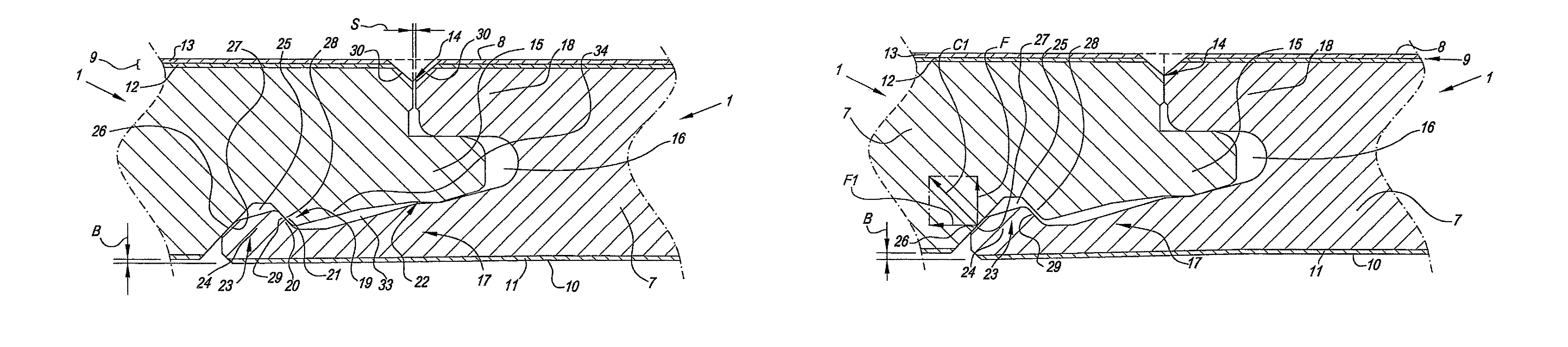
[0025]According to its fourth independent aspect, the invention also relates to a floor panel of the type having, at least at two opposite sides,
coupling means allowing that two of such floor panels can cooperate with each other, wherein these coupling means, in a coupled condition of two of such floor panels, provide for a locking in a vertical direction perpendicular to the plane defined by the coupled floor panels, as well as in a horizontal direction perpendicular to the respective sides and in the plane of the coupled floor panels, wherein said coupling means allow that two of such floor panels can be locked in a
mutual position in which the upper edges of the respective floor panels substantially are situated in the same horizontal plane, whereas at the height of these upper edges, between the respective sides, a space is present, with as a characteristic that the respective coupled floor panels in said mutual position are mutually locked in said horizontal direction free from play, and that said space defines a mutual distance of one to three millimeters between said upper edges. This particular combination between a connection that is free from play in horizontal direction, and a space S that is considerably larger than the play interspace known from the state of the art, for example, from WO 94 / 26999, may offer
special effects. Namely, by means of such floor panels, coupling means, respectively, it is possible to compose floor coverings in a repeatable manner, which floor coverings approach the appearance of a
plank floor, with gaps between the planks.
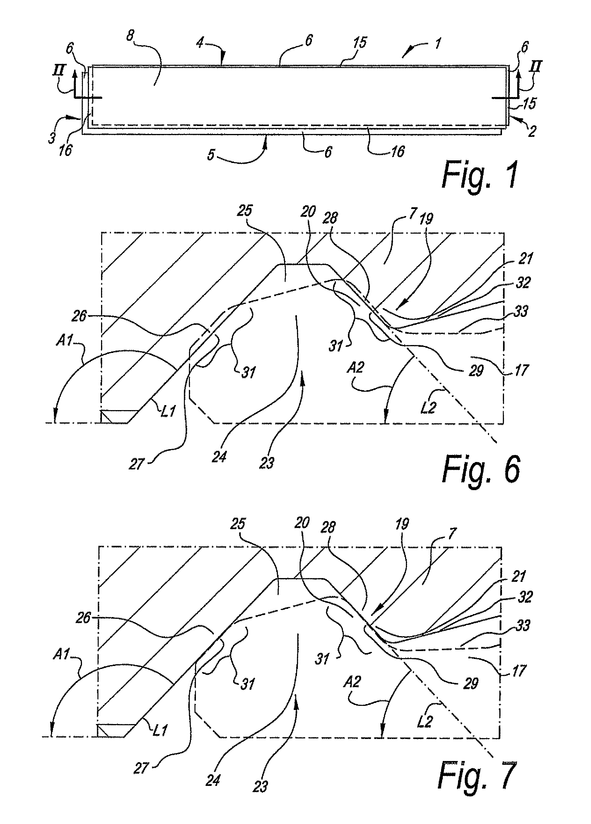
[0032]According to this fifth aspect, said coupling means may comprise positioning means, wherein these positioning means during coupling always urge, bring, respectively, two of such floor panels into an initial locked mutual position, wherein the coupled floor panels can leave said initial mutual position by shifting in a locked condition in horizontal direction towards each other or away from each other. The presence of such positioning means prevents making mistakes when installing the floor panels, whereas these floor panels still can expand and / or shrink. Of course, here the prior-described coupling means and / or positioning means may be applied.
[0049]It is evident that there where a
restoring force is mentioned, this force, according to the invention, preferably occurs before the floor panels have moved so far away from each other that they unlock, and / or before the floor panels are moved up to their mutually closest position, respectively, for example, before they have moved so close to each other that said space has disappeared. According to all aspects of the present invention and / or its preferred forms of embodiments, the possible
restoring force has a self-centering or self-positioning effect, as it urges the floor panels, when they leave the initial locked or coupled position, or any other locked position, back into the direction of this initial or other position concerned. Preferably, this restoring force is operative, on the one hand, as soon as the floor panels move away from each other from said initial or other mutual position, and on the other hand, as soon as the floor panels move towards each other from said initial mutual position. Still better, the restoring force increases with increasing distance of the floor panels from said initial or other mutual position.

