Braiding mechanism and methods of use

a tubular braid and braiding mechanism technology, applied in the field of tubular braiding apparatus and methods, can solve the problems of inability to meet the needs of most medical applications that require construction with fine wires with low tensile strength, limited speed of these machines, and general limitation of types of braiding machines

Active Publication Date: 2012-09-11
MICROVENTION INC
View PDF40 Cites 261 Cited by
  • Summary
  • Abstract
  • Description
  • Claims
  • Application Information

AI Technical Summary

Benefits of technology

[0007]The braiding apparatus described herein provides improved means of manufacturing high wire-count (also described as high picks per inch or PPI) tubular braids of small diameter filaments, and is particularly useful for the production of fine wire metallic alloy (e.g. nitinol, cobalt-chrome and platinum-tungsten) for medical applications.

Problems solved by technology

The speed of these machines is limited by the inertia of the carriers and / or changes in tension on the filaments resulting from the continuously changing radial movement towards and away from the point of braid formation.
These types of braiding machines, however, are generally limited to production of braids using lower filament count and / or generally large filaments.
See http: / / www.braider.com / About / Megabraiders.aspx These Megabraiders, however, are generally used for large structures and are not suitable for most medical applications that require construction with fine wires that have low tensile strength.
The Wardwell Braider, however, becomes unreliable when trying to braid strands or filaments of material, particularly very fine wire materials, having extremely small diameters.
The rotary technique used therein produces so much tension on the very small diameter materials, particularly at one stage of the braiding process, that such extremely fine filaments tend to break, requiring that the machine be stopped.

Method used


Image

  • Braiding mechanism and methods of use
  • Braiding mechanism and methods of use
  • Braiding mechanism and methods of use

Examples


Embodiment Construction

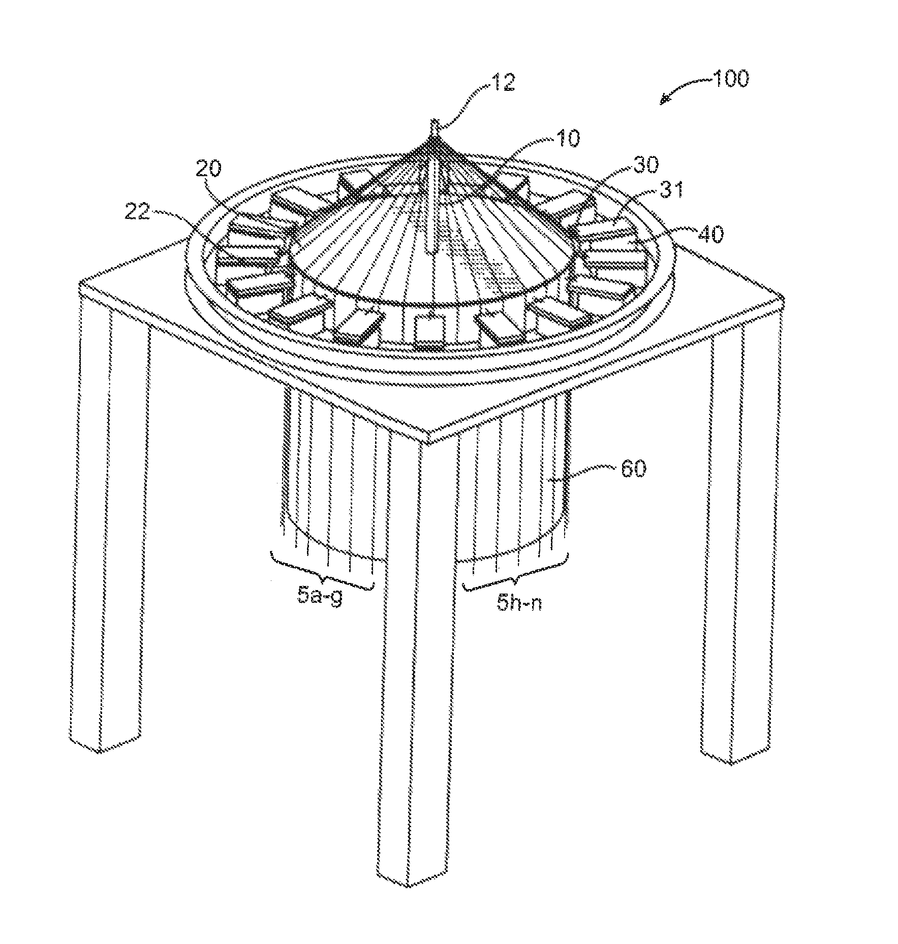
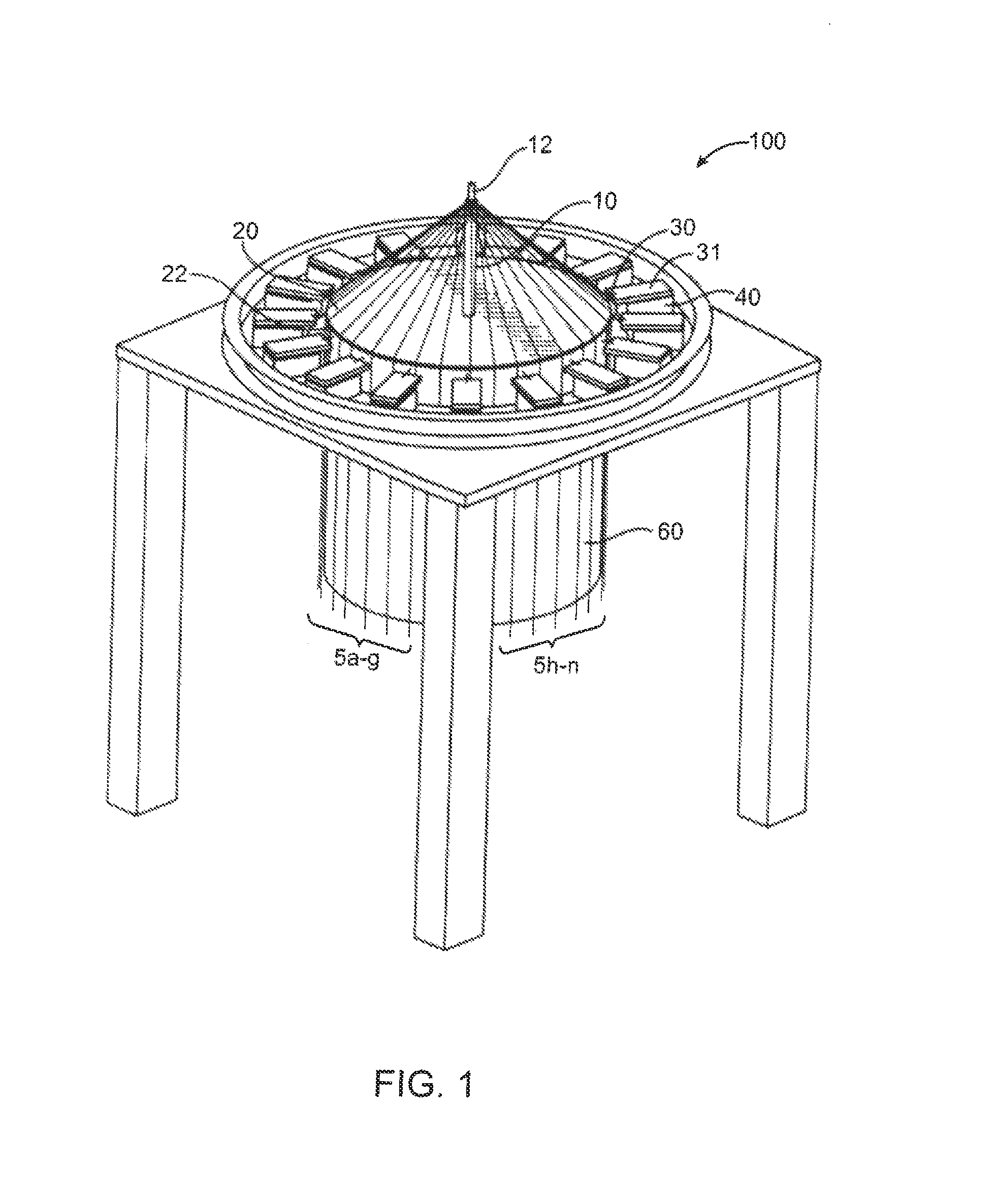
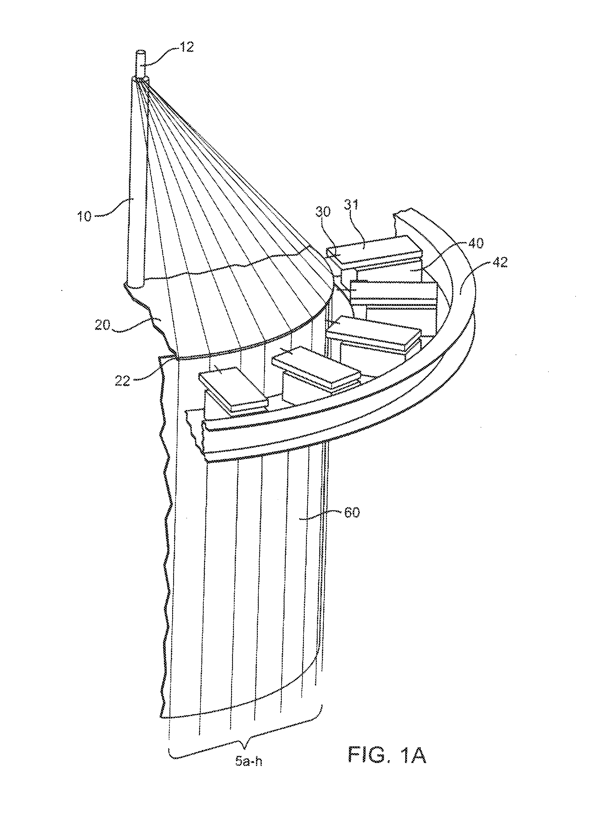
[0054]Discussed herein are devices and methods for creating a tubular braid from a plurality of filaments. Because the braiding machine individually engages a subset of the filaments and moves the engaged filaments relative to the unengaged filaments in discrete steps to interweave the filaments, it does not create the large tension spikes common to the continuous motion braiding machines. Thus, the invention is particularly useful for making braided tubes of ultra-fine filaments, in the order of ½ mil-5 mil, for example, for use in vascular implants, such as embolization devices, stents, filters, grafts, and diverters for implantation in the human body. It will be appreciated, however, that the invention could also be advantageously be used for making braids for other applications and with other sized filaments.

[0055]The ability to individually engage a subset of filaments and move the filaments in discrete steps also allows for both flexibility in the loading of the machine and in...


PUM


Abstract

A device and method for forming a tubular braid comprising a plurality of filaments. The braiding machine comprises a disc with a mandrel extending from the center in a perpendicular direction and a plurality of catch mechanisms arranged circumferentially around the edge of the disc. A plurality of filaments are temporarily affixed to the mandrel, each filament extending from the mandrel toward the edge of the disc and engaging the edge of the disc at a discrete point of engagement The plurality of catch mechanisms are attached to actuators adapted to move the catch mechanisms in a generally radial direction relative to the edge of the disc to allow the catch mechanism to engage a subset of the filaments and move the engaged filaments beyond the circumferential edge of the disc.

Description

FIELD OF THE INVENTION[0001]The invention relates to an apparatus and methods for making a tubular braid comprising a plurality of filaments, particularly small diameter wires.BACKGROUND OF THE INVENTION[0002]Braiding machines have long been used in industry, for example, to braid metallic wire into electrical or electronic cable as a protective armor or into hydraulic hose and cordage as a load bearing structure or into rope, either metallic or non-metallic.[0003]The two main kinds of braiding machines presently used are maypole-type braiding machines and internal cam rotary-type braiding machines. The maypole-type machine uses a plurality of spool carriers to carry filament bobbins in serpentine-like paths about a track plate. The track plate consists of two separate paths: each path 180 degrees out of phase from the other. One path moves clockwise, while the other path moves counter clockwise. Horn gears or notched rotors on the deck create the serpentine path. Half the carriers ...

Claims


Application Information

Patent Timeline
Patent Type & Authority Patents(United States)
IPC IPC(8): D04C3/40
CPCD04C3/42D04C3/48D04C3/40D04C1/06D10B2509/04D04C5/00D10B2509/06
Inventor MARCHAND, PHILIPPENOLTING, JOHNKENT, DARRIN J.DINH, TAN Q.TRAN, HUNG P.MILBURN, JAMESTHOMPSON, JAMES
Owner MICROVENTION INC
Why Eureka
Try Eureka