Other side tool support base and/or other side tool post mounted to casting breaking apparatus, and bearing of the other side tool support base

a technology of supporting base and other side, which is applied in the direction of bearing components, shafts and bearings, grain treatment, etc., can solve the problems of accelerating a degree of wear, less room for improvement, and the possibility of sliding face wear (loss) to be generated, so as to prevent sliding face wear and reduce wear. , the effect of effectively preventing the sliding face wear

Active Publication Date: 2012-09-11
OKUYA YASUAKI
View PDF9 Cites 6 Cited by
  • Summary
  • Abstract
  • Description
  • Claims
  • Application Information

AI Technical Summary

Benefits of technology

[0011]The invention is constructed by the constitution in which each of the sliding faces formed on both sides of the other side tool support base and / or other side tool post is formed with the cut recess streak reaching the upper and lower sides of the sliding face, the cut recess streak is subjected to overlay welding, and the overlay weld streak piece substantially in flush with the sliding face is formed by polishing means for making the overlayer of the overlay welding substantially in flush with the sliding face. Therefore, the invention is characterized in capable of achieving prevention of wear of the sliding face of the other side tool support base and / or the other side tool post, and even when a particle or a small piece of the casting waste invades a gap between the other side tool post and the side plate, the invention is capable of effectively preventing wear of the sliding face.
[0012]Next, the invention is constructed by a constitution in which both end portions in a longitudinal direction of the sliding face (direction reaching a lower end from an upper end thereof) are formed with overlay weld streak pieces substantially in flush therewith. Therefore, the invention is characterized in capable of firmly reducing wear of a portion of the other side tool post liable to receive an impact the most, and capable of effectively preventing wear of the sliding face by reducing a particle, or a small piece of the casting waste invading a gap between the other side tool post and the side plate.
[0013]The invention is further characterized in that an axially fixed portion of the other side tool support base is constituted by a metal structure, when a failure is brought about accidentally, a structure of capable of being repaired swiftly is constituted, or standardization of a maintenance thereof is achieved or the like. Further, in the kind of metal structure, there is achieved an advantage in which when a particle or a small piece of the casting waste invades an inner portion thereof, a structure of not deteriorating a function thereof is constituted, a structure of not accelerating wear of the metal can be provided or the like.
[0014]The invention achieves an advantage in which the object of the invention as further characterized above can be achieved, or a metal structure optimum and effective in achieving the object can be provided.
[0015]The invention achieves an advantage in which the object of the invention as further characterized above can be achieved, and a dust seal optimum and effective for achieving the object can be provided or the like.

Problems solved by technology

Further, according to the kind of the apparatus, the other side tool support base and / or the other tool post is brought into sliding contact with the sideplate in being made to be movable, and there is a probability of generating wear (loss) in the face to be slid (sliding face).
Further, when a particle or a small piece of the casting waste invades a gap between the other tool base and the side plate, a problem of accelerating a degree of the wear is conceivable.
However, in a metal structure of the axially fixed portion, with regard to a structure of swiftly repairing a failure when the failure is accidentally brought about, the structure is not regarded to be necessarily sufficient, or to achieve a standardization of maintenance thereof, more or less room for improvement is conceivable.
Further, according to the kind of the metal structure, there is conceivable a problem in which when a particle or a small piece of a casting waste invades an inner portion thereof, a function thereof is deteriorated, and wear of the metal is accelerated.

Method used


Image

  • Other side tool support base and/or other side tool post mounted to casting breaking apparatus, and bearing of the other side tool support base
  • Other side tool support base and/or other side tool post mounted to casting breaking apparatus, and bearing of the other side tool support base
  • Other side tool support base and/or other side tool post mounted to casting breaking apparatus, and bearing of the other side tool support base

Examples


Embodiment Construction

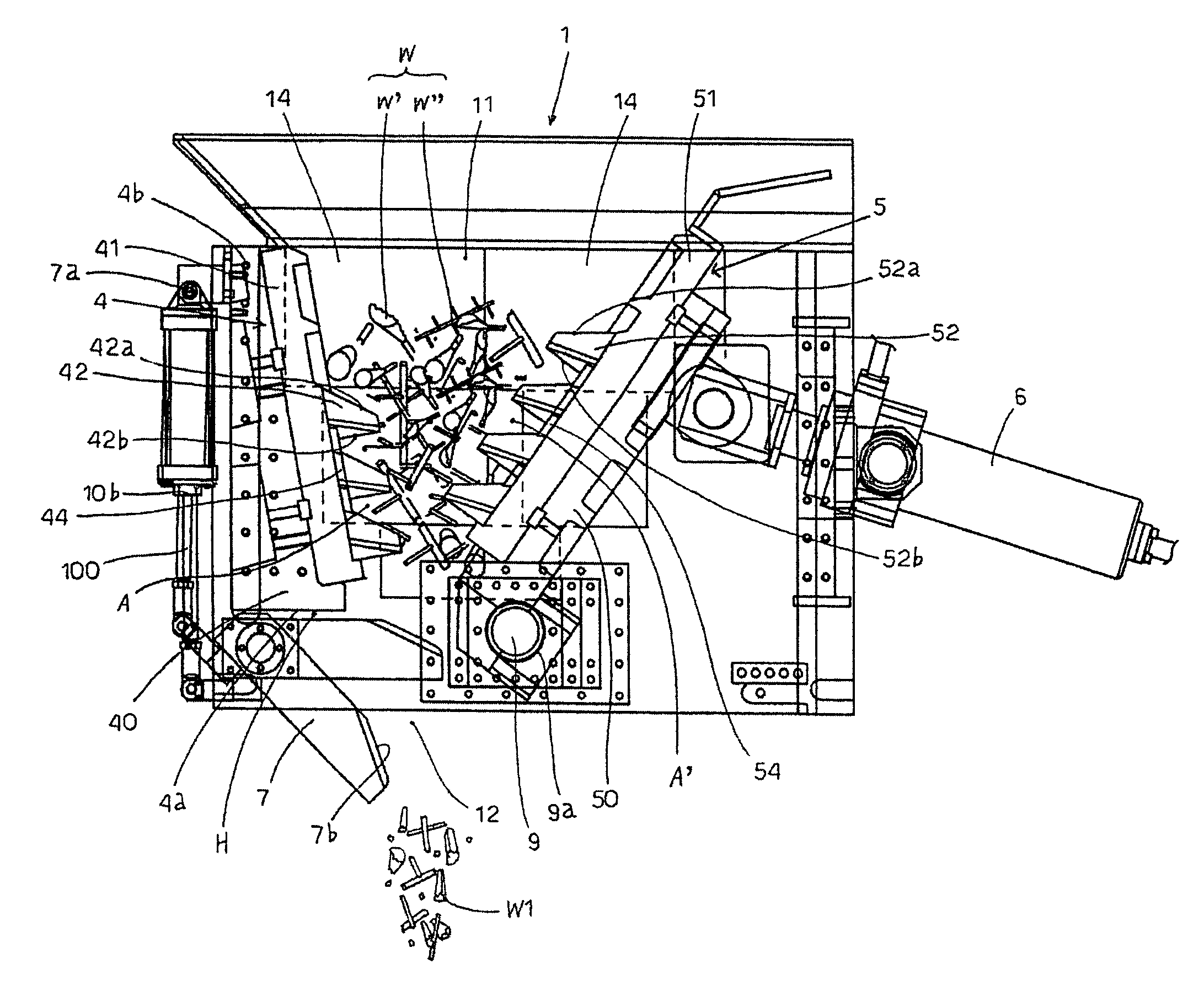
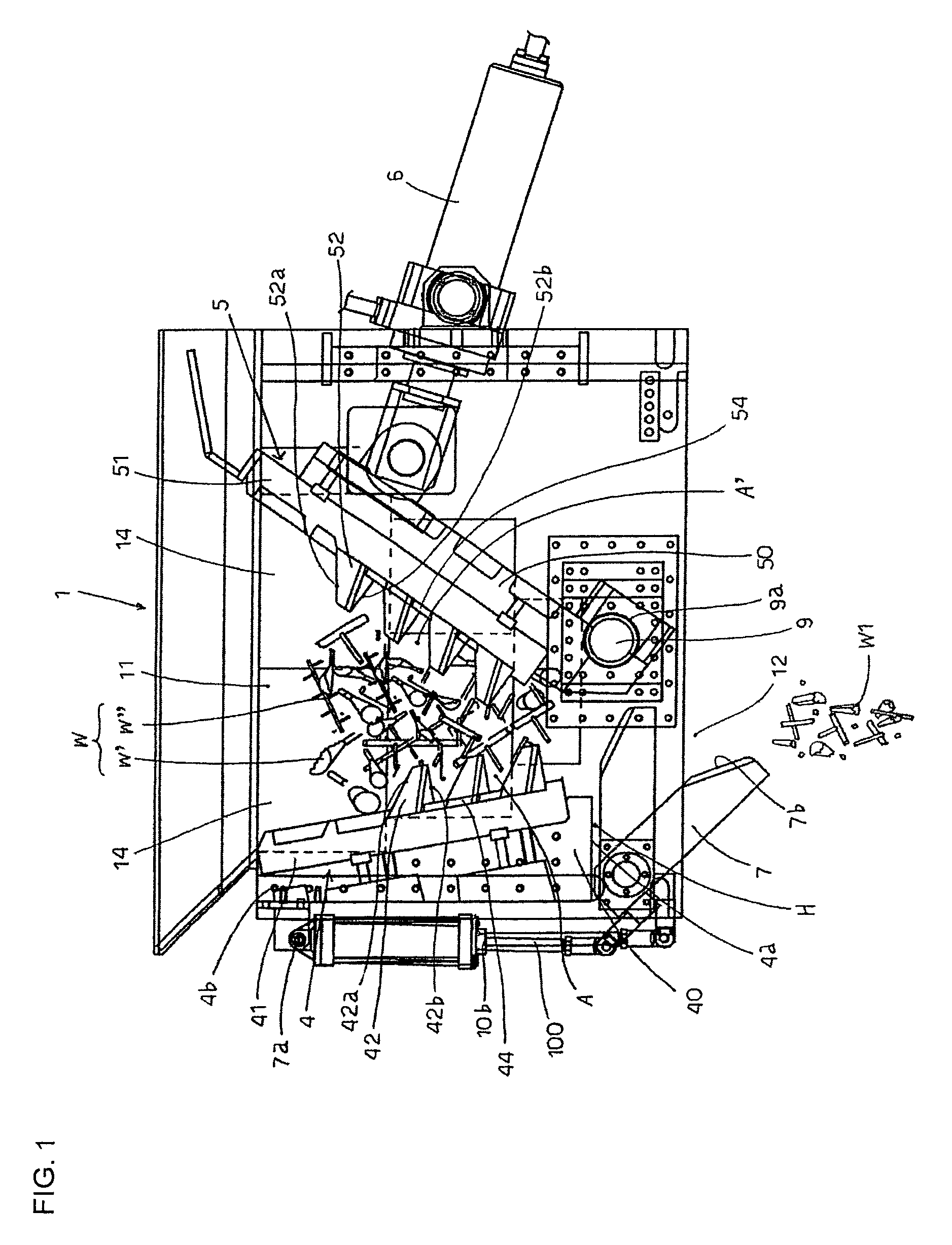
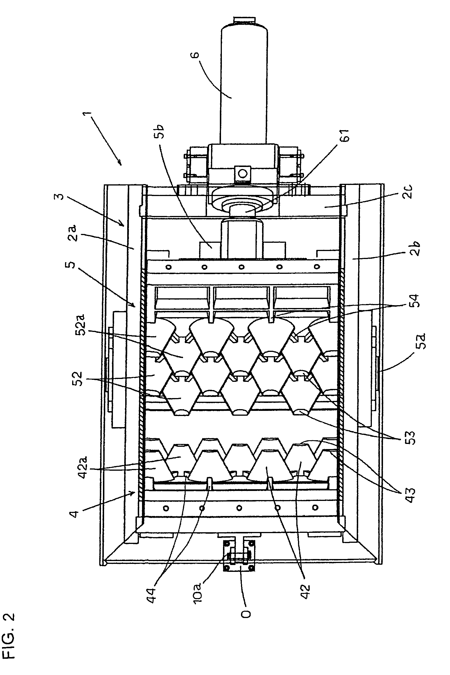
[0029]A basic structure of a breaking apparatus of the invention is shown in FIG. 1 through FIG. 4, explaining an example thereof, numeral 1 designates a breaking apparatus (crushing and / or breaking apparatus) of a casting waste, and the breaking apparatus 1 constitutes main constituent elements by a frame 3 upper and lower sides of which are opened constituted by side plates 2a, 2b and a bridging plate 2c, one side tool apparatus 4 (fixed tool apparatus) and other side tool apparatus 5 (moving tool apparatus) provided at the frame 3, a cylinder 6 of advancing and retreating the other side tool apparatus 5, and a damper 7.

[0030]First, the one side tool apparatus 4 is constituted by one side tool support base 40 provided at the frame 3 for attaching a tool post, one side tool post 41 attachably and detachably provided at the one side tool support base 40, and a number of pieces of one side tools 42 (receive tools, or press tools) for crushing / breaking in a shape of a truncated cone p...


PUM


Abstract

A tool support base and a tool post for cutting a casting, in which contact surfaces in sliding contact with both side plates are formed on both sides of the tool support base and the tool post. A cut recess is formed in the sliding contact surface so as to vertically extend in the surface. Deposit welding is applied to the cut recess and a ridge of weld deposit generally flush with the contact surface is formed by grinding means that makes the weld deposit, formed by the deposit welding, flush with the contact surface. The construction minimizes wear of the contact surface as much as possible, and even if particles of casting waste materials enter gaps between the tool support base and the tool post and the side plates, the construction can avoid wear by such particles.

Description

TECHNICAL FIELD[0001]The present invention relates to other side tool support base and / or other side tool post mounted to a casting breaking apparatus of crushing / breaking (defined as breaking) a casting waste of a sprue, a runner, a weir, a failed casting or the like, and a bearing of the other side tool support base.BACKGROUND ART[0002]With regard to other side tool support base and / or other side tool post mounted to a casting breaking apparatus, and a breaking method (crushing / breaking apparatus) related to a bearing of the other side tool support base and / or the other side tool post of the title, an invention related to a proposal of the applicant has been disclosed in Japan and United States or Europe. Explaining an example thereof, there is present “apparatus of crushing / breaking weir, runner, failed product or the like for casting by hydraulic pressure” of JP-A-6-106083, “method of breaking casting and tool structure” of JP-A-2002-224580 of Japanese Application, or “CRUSHING-...

Claims


Application Information

Patent Timeline
Patent Type & Authority Patents(United States)
IPC IPC(8): B02C1/10
CPCB02C1/04B02C1/10B02C18/02
Inventor OKUYA, YASUAKI
Owner OKUYA YASUAKI
Why Eureka
Try Eureka