
Drag-optimised ram-air duct and process for controlling a mass flow of ambient air or cooling air through a ram-air duct

a ram-air duct and mass flow technology, applied in the field of ram-air ducts, can solve the problems of increasing the aerodynamic drag of the open ram-air outlet duct, reducing the service life of the ram-air outlet duct, and reducing the maintenance cost, so as to enhance the reliability of the air-conditioning plant and reduce the maintenance cost. , the effect of minimal cooling air

Active Publication Date: 2012-09-11
AIRBUS OPERATIONS GMBH
View PDF2 Cites 13 Cited by
  • Summary
  • Abstract
  • Description
  • Claims
  • Application Information

AI Technical Summary

Benefits of technology

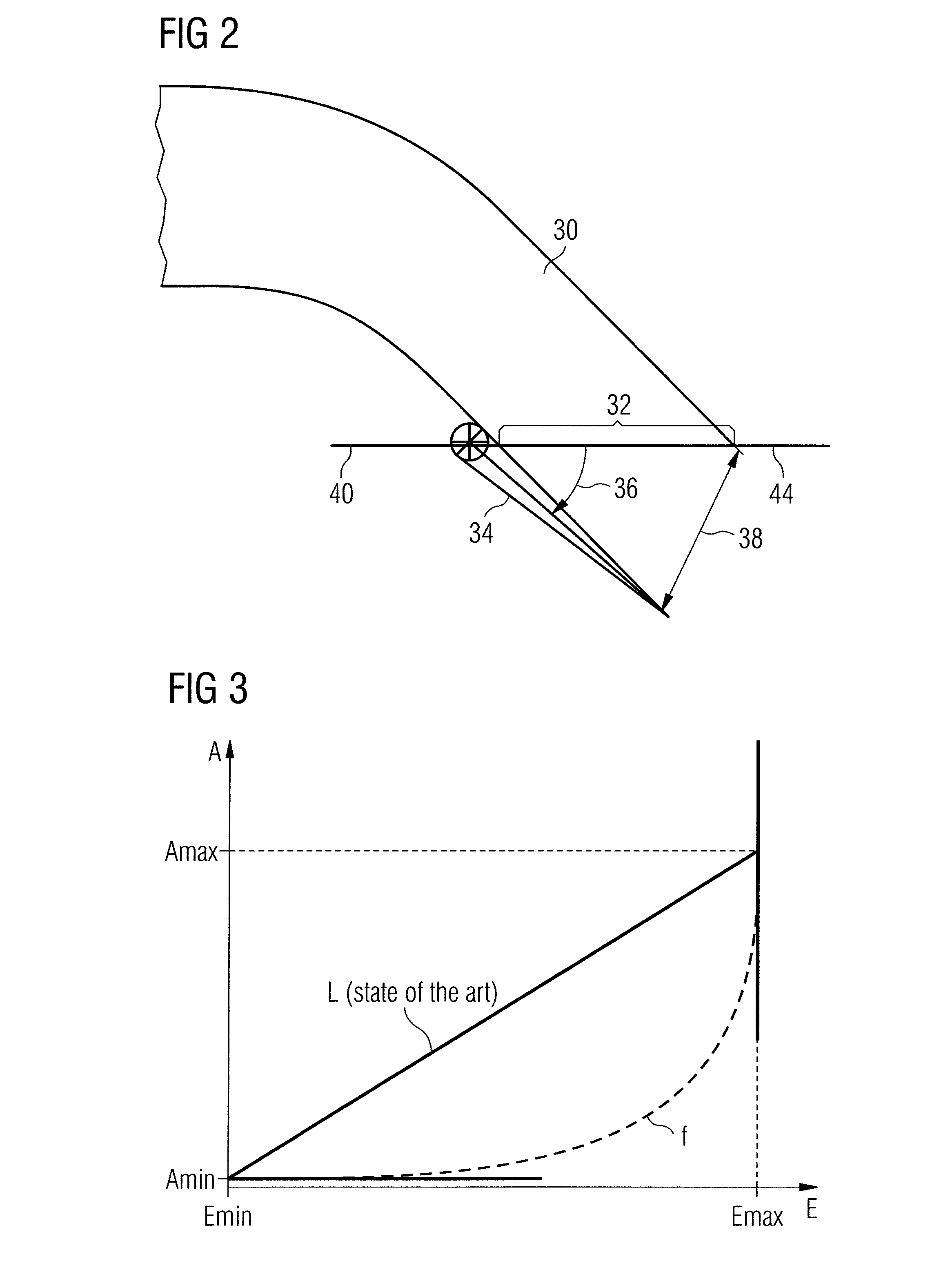
[0019]Within an inlet-parameter range in which the gradient of the function ƒ is less than the gradient of the linear function L the control of the flow of cooling air through the ram-air duct is effected more intensely by a change, of the inlet parameter than by a change of the outlet parameter. In other words, the movable element at the outlet is, in comparison with the conventional control in accordance with the linear function, retracted comparatively further than the movable element at the inlet, and the control of the amount of cooling air takes place substantially by means of the movable element at the inlet. A further advantage is that, by reason of the smaller outlet parameter in relation to the conventional control, the cooling air flows out of the ram-air outlet duct at a higher speed, generating an additional thrust.
[0025]In the ram-air duct the inlet parameter and / or the outlet parameter can be set continuously within their respective control ranges. Alternatively, a stepwise setting of the inlet parameter and / or of the outlet parameter within their respective control ranges is conceivable. In this connection, for the inlet parameter within the control range thereof a plurality of discrete inlet parameters may have been predetermined, and for the outlet parameter within the control range thereof likewise a plurality of discrete outlet parameters may have been predetermined. The respective discrete outlet parameters and the respective discrete inlet parameters can be linked together by the function ƒ. The movable elements at the inlet and outlet are brought into such respective discrete positions that the throughput of cooling air remains minimal. An associated control temperature of the air-conditioning plant may lie within a range between a minimal and a maximal value. If an actual value of the control temperature exceeds the maximal value, the movable elements at the input and at the output are opened up by a respective step into a further discrete position, or opened. If the actual value of the control temperature falls below the minimal value, the movable elements are retracted by a respective step into a further discrete position, or closed. The magnitude and the location of the range of the control temperature of the air-conditioning plant are optimised in a manner depending on the particular given conditions of the plant or of the aircraft. This type of regulation with discrete inlet parameters and outlet parameters affords the further advantage that, by virtue of slighter wear and slighter attrition, the movable elements that are moved less frequently, for example ram-air-duct flaps, enhance the reliability of the air-conditioning plant and diminish the maintenance costs for users of the aircraft that are equipped with a ram-air duct of such a type.

Problems solved by technology

Recent aerodynamic investigations have shown, in addition, that an open ram-air outlet-duct flap generates a higher additional aerodynamic drag than an open ram-air inlet-duct flap or open ram-air inlet-duct flaps.
In order to guarantee a sufficient mass flow of ambient air through the ram-air duct, in normal operation of conventionally designed ram-air ducts, and given compliance with a linear relationship between the outlet parameter and the inlet parameter, as shown in FIG. 3, it is, however, unavoidable as a rule to open the ram-air outlet-duct flap relatively wide—i.e. to position it inclined at an angle of >10° relative to a portion of the outer skin of the aircraft surrounding the ram-air outlet.
Furthermore, the ram-air outlet-duct flap projecting into the flow of ambient air flowing around the outer skin of the aircraft in flying operation of the aircraft, as well as separations of the flow of air emerging from the ram-air outlet, cause turbulences in the flow of ambient air flowing around the outer skin of the aircraft in flying operation of the aircraft, which further increase the additional aerodynamic drag of the aircraft caused by the ram-air duct.

Method used


Image

  • Drag-optimised ram-air duct and process for controlling a mass flow of ambient air or cooling air through a ram-air duct
  • Drag-optimised ram-air duct and process for controlling a mass flow of ambient air or cooling air through a ram-air duct
  • Drag-optimised ram-air duct and process for controlling a mass flow of ambient air or cooling air through a ram-air duct

Examples


Embodiment Construction

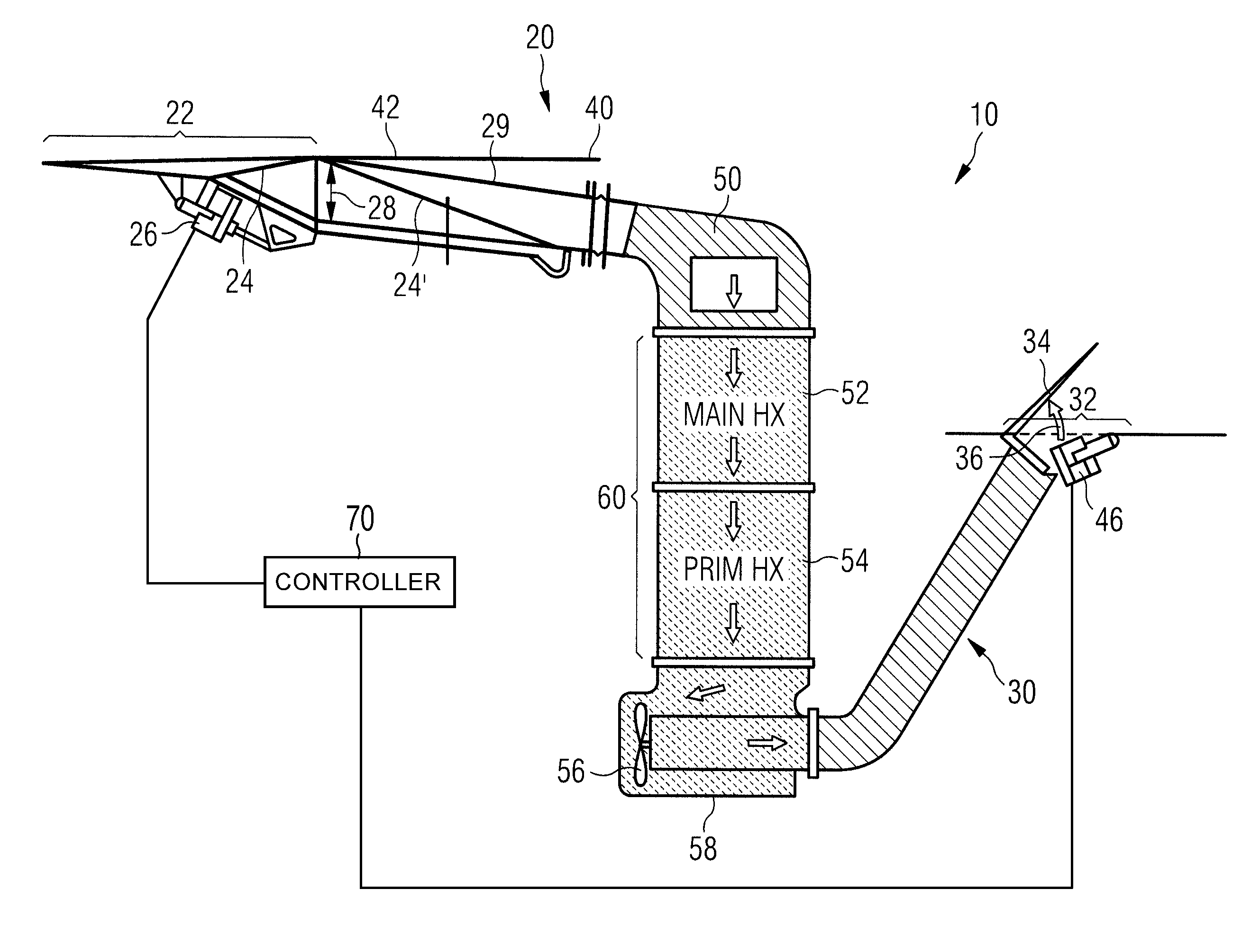
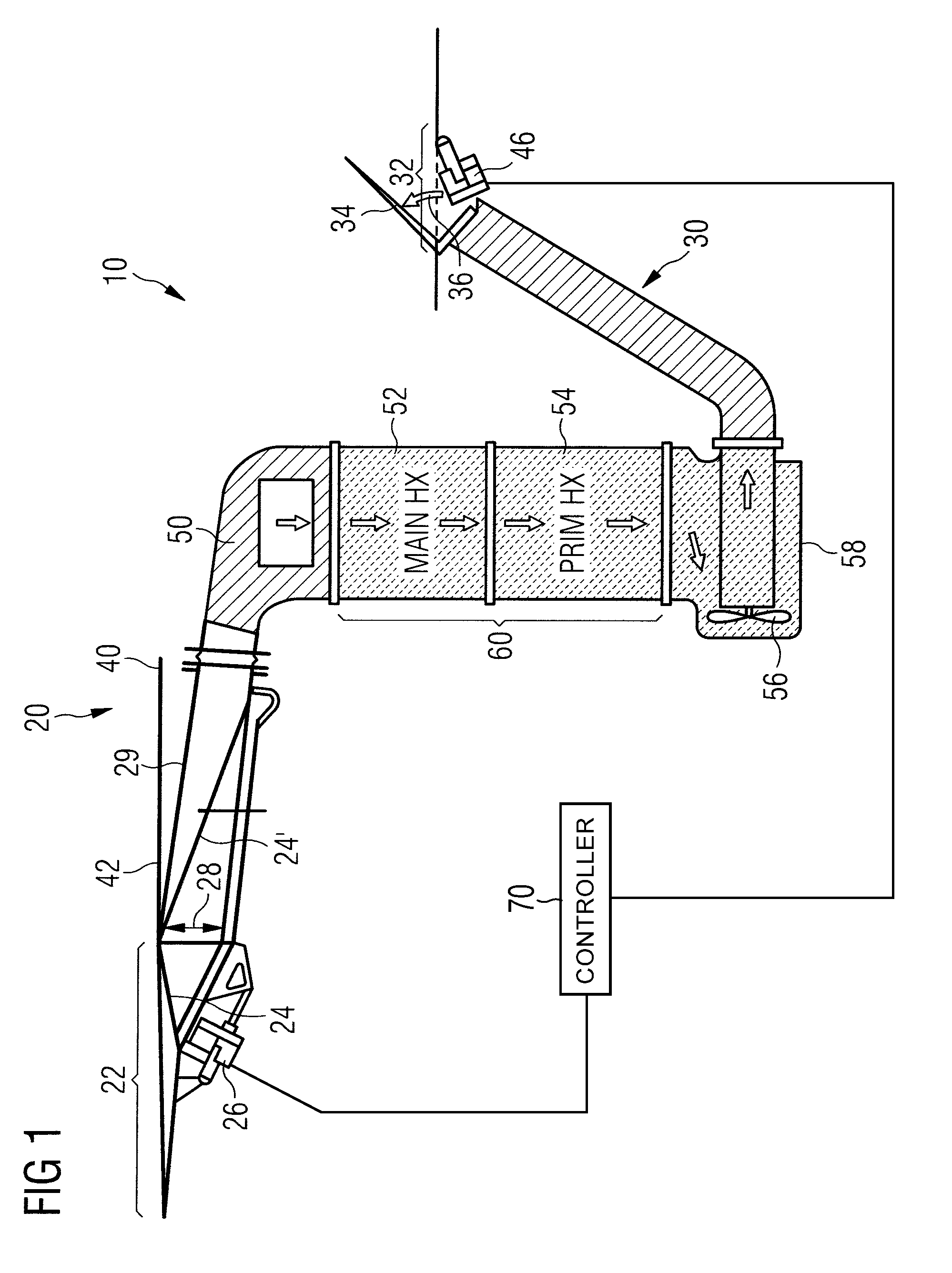
[0052]FIG. 1 shows in exemplary manner a ram-air duct 10 of an aircraft air-conditioning plant such as is employed in modern passenger aircraft. The ram-air duct 10 includes a ram-air inlet duct 20, an adapter piece, called ram-air-duct plenum 50, attached downstream of said ram-air inlet duct, a ram-air active portion 60 attached downstream of said ram-air-duct plenum, in which the heat-exchangers, in particular a main heat-exchanger 52 and a primary heat-exchanger 54, of the aircraft air-conditioning plant are arranged and which is perfused by the cold outside air by way of coolant, an adapter, called pack plenum 58, arranged downstream of the ram-air active portion 60, in which, in particular, a fan (ACM fan) 56 is arranged, as well as a ram-air outlet duct 30 arranged downstream of the adapter piece.

[0053]The ram-air inlet duct 20 exhibits at its upstream end a NACA inlet 22 recessed in the outer skin 42 of the aircraft. Furthermore, the ram-air inlet duct 20 includes a ram-air-...


PUM


Abstract

A ram-air duct includes a ram-air inlet duct and a ram-air outlet duct arranged downstream of the ram-air inlet duct and in fluid communication with the ram-air inlet duct. At an inlet of the ram-air inlet duct, a first movable element is arranged and adapted to set an inlet parameter of the inlet. At an outlet of the ram-air outlet duct, a second movable element is arranged and adapted to set an outlet parameter of the outlet. The outlet parameter and the inlet parameter are linked together by a function, so that an outlet parameter corresponding to a value of the function is assigned to each inlet parameter. A controller implements the control function by actuating movements of the first and second movable elements.

Description

CROSS-REFERENCE TO RELATED APPLICATIONS[0001]This application claims priority to U.S. Provisional Patent Application No. 61 / 167,930 and German Application No. 10 2009 017 040.5, both filed on Apr. 9, 2009.TECHNICAL FIELD[0002]The present invention relates to a ram-air duct for supplying ambient air in an aircraft, and to a process for controlling a mass flow of ambient air or cooling air through a ram-air duct.BACKGROUND[0003]Ram-air ducts with an air inlet and with a ram-air inlet duct extending downstream of the air inlet, with a ram-air active portion extending downstream of the inlet duct and also with a ram-air outlet duct extending downstream of the ram-air active portion, with an air outlet at the downstream end of said ram-air outlet duct, are employed in modern aircraft for the purpose of supplying various systems located on board the aircraft, such as an air-conditioning system for example, with ambient air. In the ram-air active portion there may be arranged, for example,...

Claims


Application Information

Patent Timeline
IPC IPC(8): B64D33/02
CPCB64D13/00B64D2241/00Y02T50/56Y02T50/50Y10T137/0645
Inventor SCHERER, THOMASSOLNTSEV, ALEXANDERSCHMIDT, RUEDIGER
Owner AIRBUS OPERATIONS GMBH
Learn More