Drive system for pivotal and/or slidable doors or for entry and exit facilities with improved position acquisition

a technology of pivotal and/or sliding doors and drive systems, which is applied in the direction of monocoque constructions, ac motor stoppers, vehicle bodies, etc., can solve the problems of complicated mechanical adjustment, inapplicability, and inability to apply the limit switch

Active Publication Date: 2012-09-11
GEBR BODE GMBH & CO KG
View PDF18 Cites 3 Cited by
  • Summary
  • Abstract
  • Description
  • Claims
  • Application Information

AI Technical Summary

Benefits of technology

[0010]The absolute value encoder, in a further advantageous embodiment, acquires the pivoting or sliding movement without contact. Malfunction immunity can thus be increased. For example, the absolute value encoder works in accordance with an optical or magnetic principle.
[0013]Alternatively, the absolute value encoder is flange-connected to a pin that fixes the pivoting movement of the door, ramp, tread or the like. Therefore, comparatively cheaper single-turn encoders can be used. In addition, a very exact and reproducible position acquisition and thus, if necessary, control of the movement is achieved because of the direct arrangement of the encoder on the moving element, i.e. the door, ramp, tread etc., so that the clearance in the mechanical system or gear unit transmitting the drive force can be compensated. Furthermore, possible material fractures within the mechanical system or the gear unit can be recognized and reported, for example because the encoder does not detect that the reference position is reached in spite of an activation of the actuator or drive motor for a longer period of time.
[0014]In another advantageous embodiment, the evaluation unit is programmable. For example, at least the non-volatile memory for recording the reference values is programmable; the non-volatile memory is, for example, an EEPROM or NV-RAM. The reference values can thus be replaced particularly easily for an adjustment. The evaluation unit is programmed, for example, by means of a BUS system, such as the CAN bus.

Problems solved by technology

Moreover, the technical drawbacks connected with the limit switches, such as complicated mechanical adjustment and a malfunction susceptibility that remains because of mechanical triggering, do not apply.
Furthermore, in the case of a possibly necessary adjustment, only the replacement of the at least one reference value stored in the non-volatile memory is required, without any mechanical adjustment being required, which is time-consuming and thus accompanied by long down times. In one embodiment, the output signal, which is dependent on the result of the comparison of the momentary position with the reference position, is supplied to a monitoring device that displays, on a system panel, for example in the driver's cab, the corresponding position of the door, tread or ramp, or the fact that an associated final position has been reached.

Method used


Image

  • Drive system for pivotal and/or slidable doors or for entry and exit facilities with improved position acquisition
  • Drive system for pivotal and/or slidable doors or for entry and exit facilities with improved position acquisition
  • Drive system for pivotal and/or slidable doors or for entry and exit facilities with improved position acquisition

Examples


Embodiment Construction

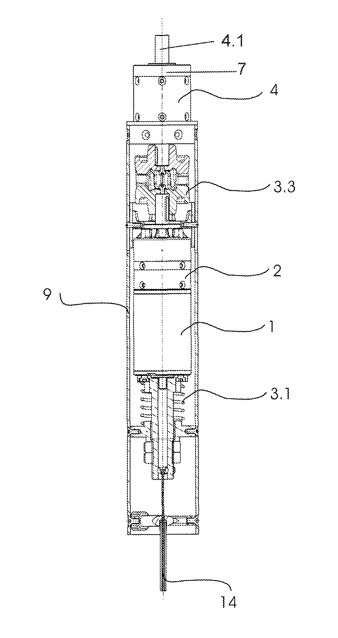
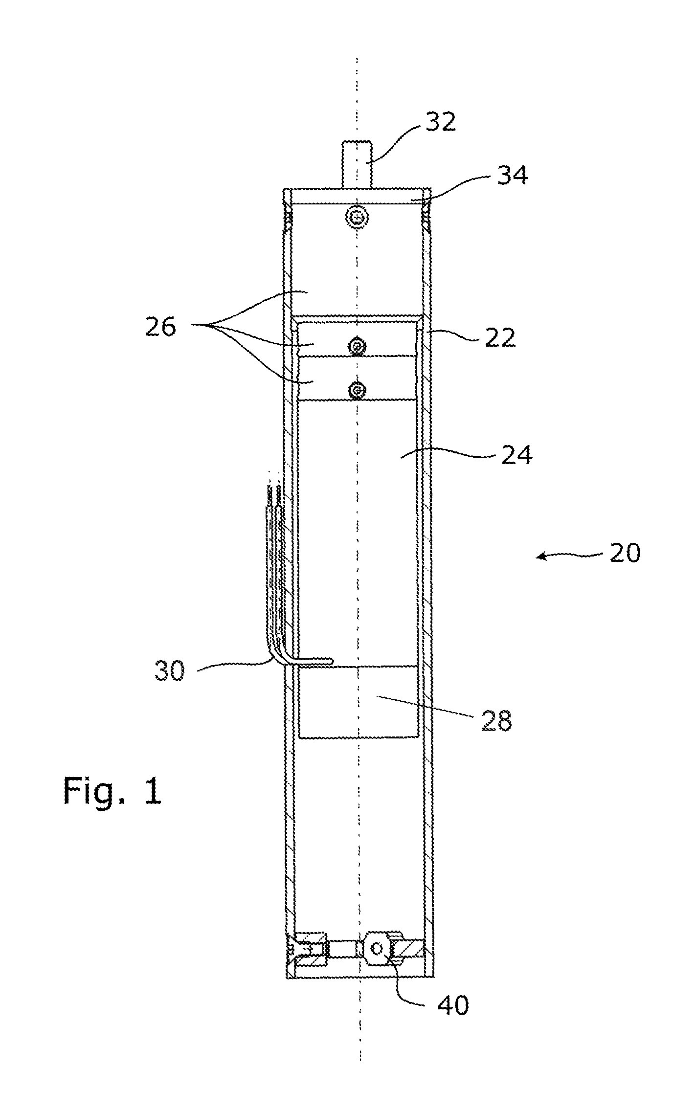
[0021]FIG. 1 shows a drive apparatus 20 configured as a compact drive for a passenger door, in which an electrical drive motor 24 and a reduction gear unit 26, which is shown as a three-part planetary gear unit, are disposed in the axial direction one behind the other within a slim housing 22 formed in a tubular manner. The drive motor 24 is followed by a brake 28, which is also accommodated within the housing 22 and which can be configured as a “low active brake” that engages under spring force and can be released electromagnetically. Electrical connectors 30 of the drive motor 24 are also shown. The reduction gear unit 26 is configured to be non-self-locking.

[0022]Preferably, the drive apparatus 20 is accommodated in a rotation post which is not shown. A driven member (which is not visible) of the drive motor 24 is connected with an input element (which also is not visible) of the reduction gear unit 26, the output element 32 of which is connected with an input element or an actua...


PUM


Abstract

A drive system for an entry / exit facility with at least one pivotably and / or slidably mounted door, ramp, tread or the like of a passenger transport vehicle, the system including at least one actuator or drive motor and a mechanical system driven by it and / or a gear unit for effecting the pivoting or sliding movement of the door, ramp, tread or the like, with an absolute value encoder for acquiring a momentary position during the pivoting or sliding movement, where an evaluation unit is configured to compare the momentary position with at least one reference position stored in a non-volatile memory of the evaluation unit in order to generate an output signal dependent thereon, and the absolute value encoder is flange-connected to a pin that fixes the pivoting movement of the door, ramp, tread or the like, and the gear unit includes a first reduction gear unit, a second reduction gear unit, and a controllable coupling is provided between the reduction gear units.

Description

TECHNICAL FIELD[0001]The invention generally relates to a drive system for an entry / exit facility with at least one pivotably and / or slidably mounted door, ramp, tread or the like of a passenger transport vehicle, an entry / exit facility provided therewith as well as a passenger transport vehicle equipped therewith.BACKGROUND[0002]A drive system of this type generally comprises at least one actuator or a drive motor and a mechanical system driven by it, and / or a gear unit for effecting the pivoting or sliding movement of the door, ramp, tread or the like.[0003]Acquiring the pivoting movement of the mechanical system or of the gear unit by means of, for example, a potentiometer pick-off is known. Such a potentiometer assembly has proven in practice not to be sufficiently wear-resistant and robust in order to satisfy the high safety requirements in passenger transportation. Moreover, it is known to control or at least monitor the pivoting or sliding movement by means of switching conta...

Claims


Application Information

Patent Timeline
Patent Type & Authority Patents(United States)
IPC IPC(8): B60J1/08
CPCE05F15/614E05Y2201/244E05Y2201/434E05Y2600/20E05Y2800/11Y10T74/18568E05Y2900/51E05Y2400/326E05Y2800/25
Inventor HARDING, ALFONSMULLER, DIRKMEYERROSE, KLAUS
Owner GEBR BODE GMBH & CO KG
Why Eureka
Try Eureka