
Method and equipment for making abrasive particles in even distribution, array pattern and preferred orientation

a technology of abrasive particles and equipment, applied in the direction of grinding devices, manufacturing tools, other chemical processes, etc., can solve the problems of reducing work efficiency, shorten deficient above-mentioned methods, and achieves the effects of prolonging the product life, high efficiency and reliability, and simple operation

Active Publication Date: 2012-09-11
JIANGSU TIANYI ULTRA FINE METAL POWDER
View PDF2 Cites 30 Cited by
  • Summary
  • Abstract
  • Description
  • Claims
  • Application Information

AI Technical Summary

Benefits of technology

The equipment ensures accurate and efficient distribution of abrasive particles, enhancing product life and work efficiency by achieving ideal density, uniformity, and orientation, thereby fully utilizing abrasive materials.

Problems solved by technology

There are many shortages for this kind of products, such as uneven distribution of abrasive materials, accumulation, partial separating out, etc. and results wasting of abrasive materials, shortening of product life as well as reducing of work efficiency.
However, the above-mentioned methods are deficient.
For example, the manual method is very time-consuming and cannot be used in large-scale manufacture.
In the process of brazing method, temperature is so high that the solder is melted to drive abrasive particles displacement; it results in heaping, uneven distribution, and bed tropism.
Template layout method cannot dispose abrasive particles to a right position, still have displacement and heaping when laying abrasive materials.
Glue water method needs complex equipment.
Also, glue water method will pollute abrasive particles and matrix.
Negative pressure adsorption method needs complex equipment too, as the abrasive particles have special and differ shape, the acetabula is hard to satisfy the requirements of products.

Method used


Image

  • Method and equipment for making abrasive particles in even distribution, array pattern and preferred orientation
  • Method and equipment for making abrasive particles in even distribution, array pattern and preferred orientation
  • Method and equipment for making abrasive particles in even distribution, array pattern and preferred orientation

Examples


Embodiment Construction

[0019]With reference to the attached drawings and the embodiments of the present invention, the equipment of the present invention is explained as follows.

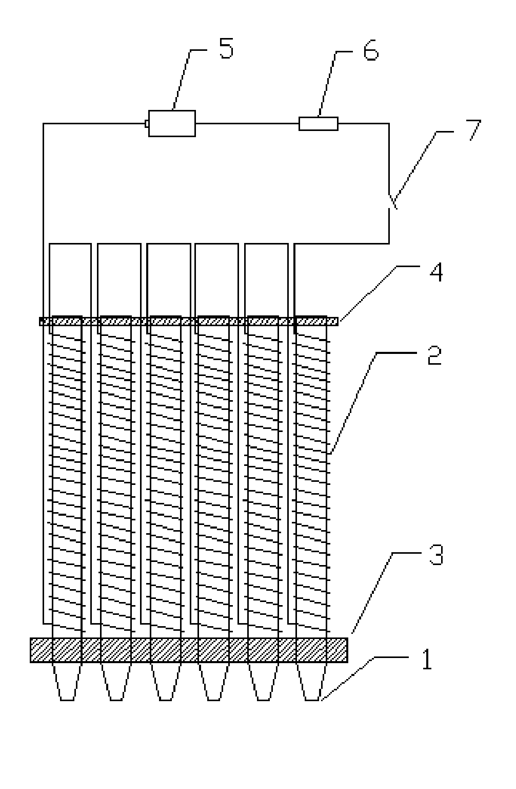
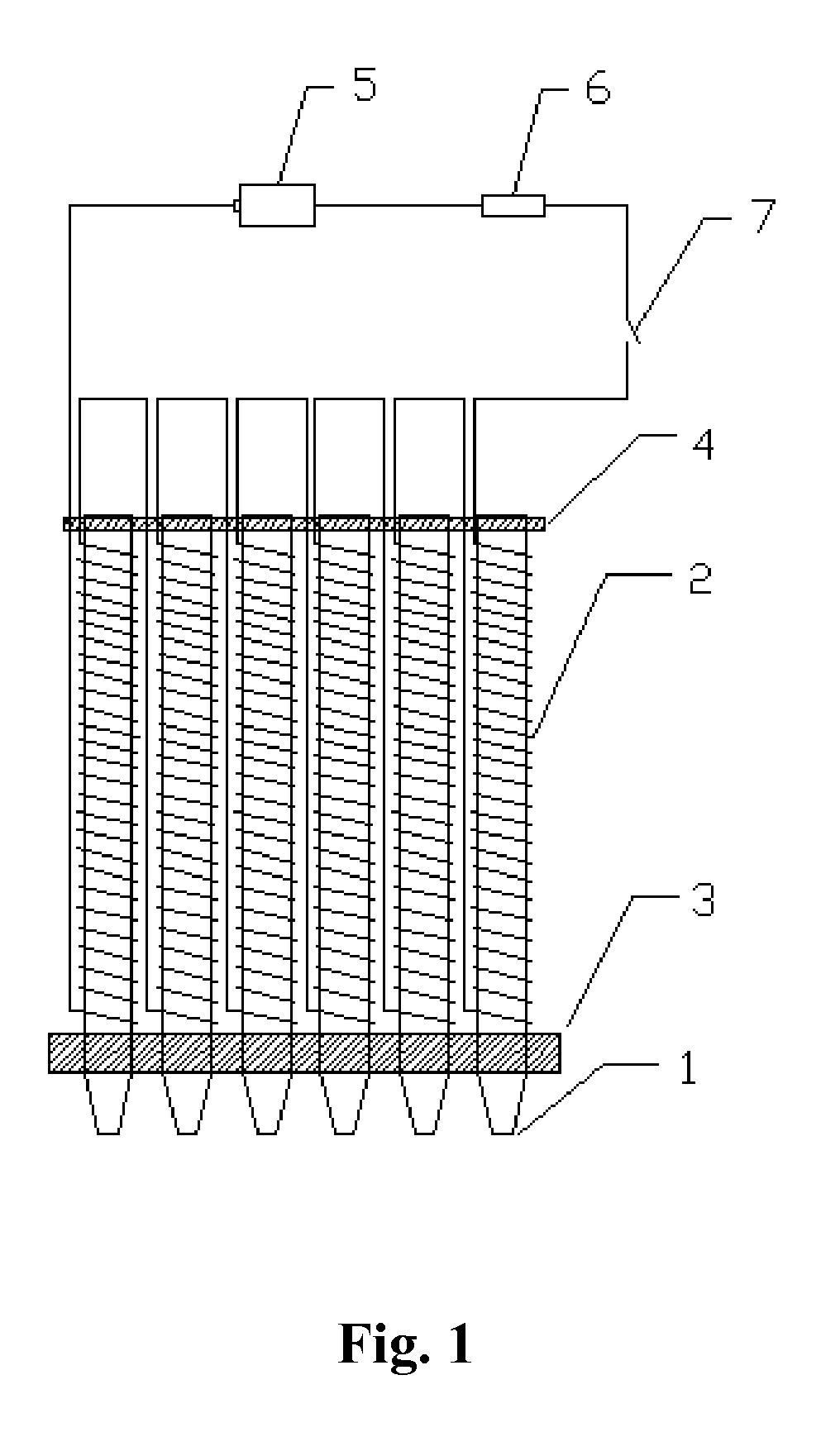
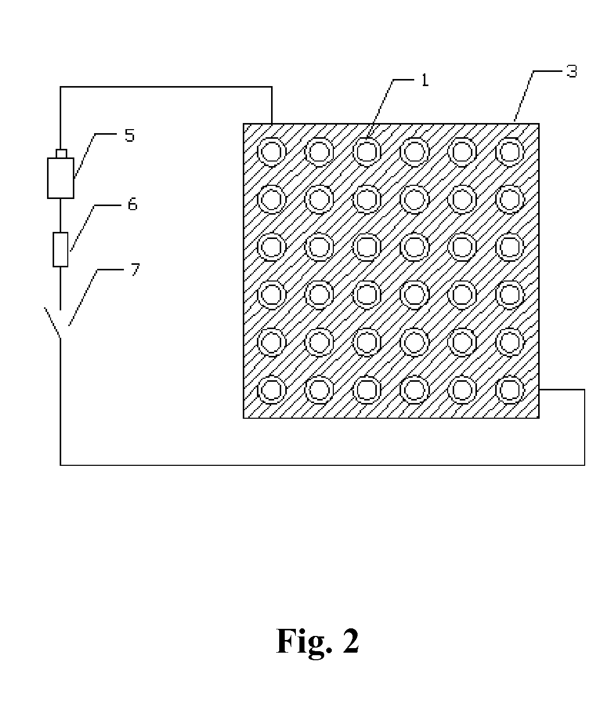
[0020]Refer to FIGS. 1, 2 and 3; this device is composed of an absorbing releasing apparatus, and a blind hole feeding tropism board. The absorbing releasing apparatus is composed of a plurality of acicular soft magnetic metallic sticks 1, a nether stator of soft magnetic metallic stick 3, an upper stator of soft magnetic metallic sticks 4 and windings 2. Each acicular soft magnetic metallic stick is wound with a winding 2. The plurality of acicular soft magnetic metallic sticks is fixed on the upper and nether stators of soft magnetic metallic sticks. The winding 2, power supply 5, resistor 6 and switch 7 form an electric circuit. All above mentioned parts compose of the absorbing releasing apparatus. The blind holes 8 are distributed on the blind hole feeding tropism board 10.

[0021]In order to improve operation accuracy for the ...


PUM

PropertyMeasurementUnit
soft magneticaaaaaaaaaa
resistanceaaaaaaaaaa
densityaaaaaaaaaa

Abstract

An equipment for making abrasive particles in even distribution, array pattern and preferred orientation comprises an adsorbing releasing apparatus being composed of a plurality of acicular soft magnetic metallic sticks, an upper and a lower stators, and a plurality of windings. Each winding forms an electric circuit through a electrical source, a resistance, and a switch a plurality of blind holes being distributed on face of the blind hole feeding tropism board. Using electric current to form magnetic field for the acicular soft magnetic metallic sticks absorb or release abrasive particles plated with soft magnetic materials. The equipment is simple, convenient in operation, high in efficiency and reliability. The equipment makes abrasive particles in matrix with an ideal state in distributing density, uniformity, arrange, and tropism. Thereby, the function of the abrasive materials is fully exerted and the life of products is prolonged.

Description

CROSS REFERENCE TO RELATED APPLICATION[0001]This application claims the priority of Chinese patent application No. 200710022816.4 filed on May 23, 2007, which is incorporated herein by reference.FIELD OF THE INVENTION[0002]This invention relates to equipment for making abrasive particles in even distribution, array pattern and preferred orientation. Especially, relates to a method that turning on or turning off electric current makes a plurality of acicular soft magnetic metallic sticks carrying magnetic field or losing magnetic field thereby absorbs or drops abrasive particles plated with soft magnetic materials to actualize the even distribution, array pattern and prepared orientation of abrasive particles.BACKGROUND OF THE INVENTION[0003]Techniques for making traditional abrasive products such as diamond abrasive wheel, abrasive cutting as knife-edge, and grinding products are that first mix abrasive material as agglomerate, and then sinter them together. The distribution of abra...

Claims


Application Information

Patent Timeline
Patent Type & Authority Patents(United States)
IPC IPC(8): B24D3/14C09C1/68C09K3/14B05C11/02
CPCB24D18/00C09K3/1409B22F1/02B22F2998/00C22C2202/02B22F1/18B24D3/00B24D5/00B24D7/00
Inventor GAO, WEIXING
Owner JIANGSU TIANYI ULTRA FINE METAL POWDER
Learn More