Image stabilizer for optical instrument

a technology of image stabilizer and optical instrument, which is applied in the field of image stabilizer, can solve the problems of affecting the smooth shift of optical elements, affecting the followability of the holder to the actuator, and the size of the image stabilizer type, so as to reduce the number of parts, and improve the accuracy of the image stabilizer

Active Publication Date: 2012-09-11
FUJIFILM CORP
View PDF20 Cites 39 Cited by
  • Summary
  • Abstract
  • Description
  • Claims
  • Application Information

AI Technical Summary

Benefits of technology

[0012]An object of the present invention is to provide an image stabilizer in which a pair of leaf springs for holding an optical element movably in a plane orthogonal to a photography optical axis is disposed in parallel with each other with great precision.
[0013]An image stabilizer according to the present invention includes a base block fixed to an optical instrument, an optical element holder for holding an optical element disposed on an optical axis of the optical instrument, an intermediate member disposed outside the optical element holder, a rectangular frame-shaped first sheet metal member fixed to the optical element holder and the intermediate member, a rectangular frame-shaped second sheet metal member fixed to the intermediate member and the base block, and an actuator. The first sheet metal member has a pair of first leaf springs that is formed by bending opposed two sides of the first sheet metal member in parallel with the optical axis and in parallel with each other. The pair of first leaf springs is elastically deformable in a first direction in a plane orthogonal to the optical axis. The second sheet metal member has a pair of second leaf springs that is formed by bending opposed two sides of the second sheet metal member in parallel with the optical axis and in parallel with each other. The pair of second leaf springs is elastically deformable in a second direction transverse to the first direction in the plane orthogonal to the optical axis. The actuator shifts the optical element through the optical element holder, while bending the first leaf springs or the second leaf springs, to counteract a shake in the first direction or the second direction.
[0020]Another image stabilizer according to the present invention includes a base block fixed to an optical instrument, an optical element holder for holding an optical element disposed on an optical axis of the optical instrument, an integrated sheet metal member fixed to the optical element holder and the base block, and an actuator. The integrated sheet metal member has a pair of mutually-parallel first leaf springs and a pair of mutually-parallel second leaf springs that are formed by bending a single sheet of metal. The pair of first leaf springs is elastically deformable in a first direction in a plane orthogonal to the optical axis. The pair of second leaf springs is elastically deformable in a second direction in the plane orthogonal to the optical axis. The actuator shifts the optical element through the optical element holder, while bending the first leaf springs or the second leaf springs, to counteract a shake of the optical instrument in the first direction or the second direction.
[0021]According to the present invention, the pair of leaf springs can be disposed in parallel with each other with great precision. This allows smooth bending of the leaf springs, and leads to improvement in the accuracy of the image stabilizer. Also, use of the integrated sheet metal member, into which the two pairs of leaf springs are integrated, allows significant reduction in a parts count.

Problems solved by technology

However, wobble and large friction occurring between the guide shaft and the bearing degrades the followability of the holder to the actuator.
This type of image stabilizer, however, is large in size in the direction of the photography optical axis.
If the leaf springs are not in parallel, one leaf spring inhibits elastic bending of the other leaf spring, and interferes with the smooth shift of the optical element.
The image stabilizer according to the Japanese Patent Laid-Open Publication No. 06-046314, however, has difficulty in precisely placing the pairs of leaf springs in parallel due to the adverse effects of dimensional accuracy of the fixed and movable pieces and attachment accuracy of the leaf springs.
Thus, the leaf springs have a limitation in reducing their thicknesses, and cannot easily have appropriate elasticity.
In the insert molding, the pair of leaf springs is hard to precisely set in a mold in parallel with each other.
Even with the use of the U-shaped leaf spring, the pair of leaf springs is still hard to precisely dispose in parallel with each other, because two parallel sides of the U-shaped leaf spring tend to be open.
However, misalignment between the coil and the magnet, deflection of the leaf spring frame or the like causes generation of the driving force in an inappropriate direction, that is, a direction to rotate the circuit board.
Application of the driving force in such a direction to the rectangular leaf spring frame results in deformation of the whole leaf spring frame.

Method used


Image

  • Image stabilizer for optical instrument
  • Image stabilizer for optical instrument
  • Image stabilizer for optical instrument

Examples


first embodiment

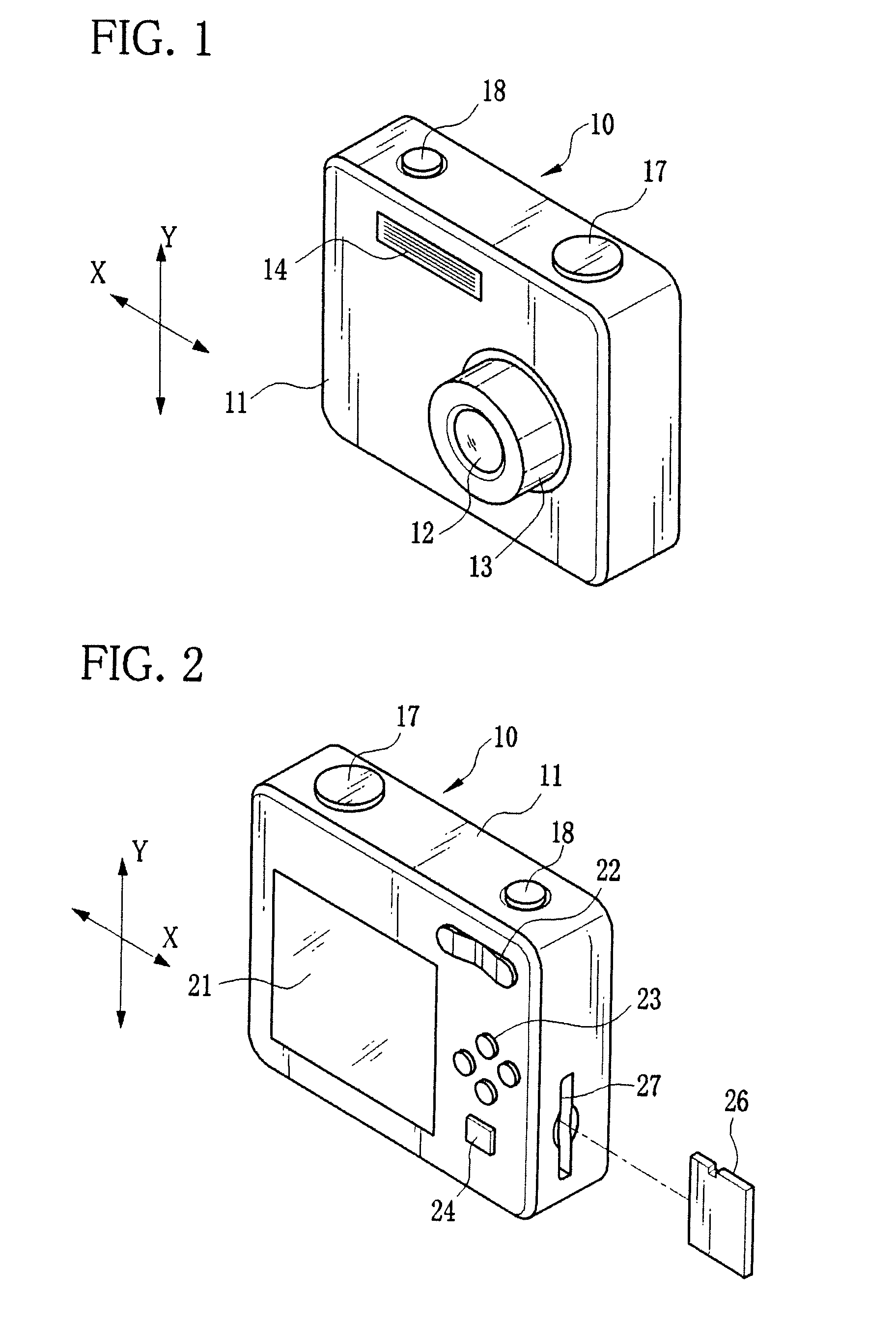
[0036]As shown in FIG. 1, a digital still camera 10 has a lens barrel 13 for containing an optical system 12, a flashlight emitter 14 for applying flashlight to an object and the like in a front face of a camera body 11.

[0037]On a top face of the camera body 11, there are provided operating members including an operation dial 17 and a shutter button 18. The operation dial 17 is used for turning the power on and off, and switching an operation mode (among a photographing mode, a playback mode and the like). The shutter button 18 is a two-step push switch, and used for taking an image. Upon turning on a first-step switch SW1 by a half press of the shutter button 18, the digital still camera 10 makes preparation for image taking (exposure setting and focusing). After that, when a second-step switch SW2 is turned on by a full press of the shutter button 18, the digital still camera 10 captures a still image and stores image data on a memory card 26.

[0038]As shown in FIG. 2, a liquid cry...

second embodiment

[0079]In a second embodiment, the first sheet metal member and the second sheet metal member are integrally formed into one body by bending a single sheet of metal, for the purpose of further improving orthogonality between the horizontal leaf springs and the vertical leaf springs and facilitating assembly. The same reference numbers as the first embodiment indicate substantially the same elements or parts, and description thereof will be omitted.

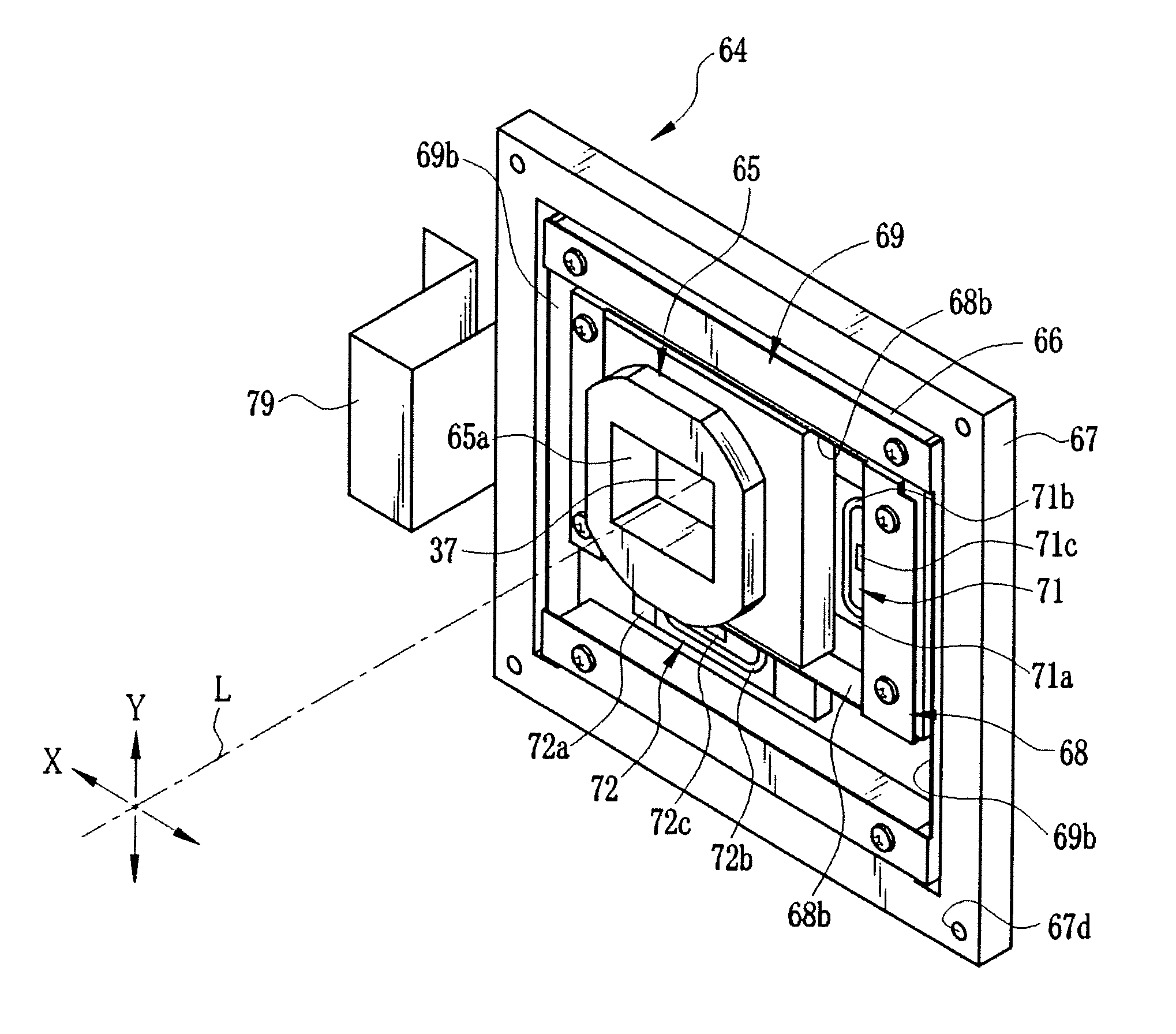
[0080]In an integrated sheet metal member 90 made of a metal leaf spring material, as shown in FIG. 9, a coupling section 91 corresponding to the intermediate member 66 couples the first sheet metal member 68 and the second sheet metal member 69 according to the first embodiment. The integrated sheet metal member 90 has a pair of horizontal leaf springs 68b extending in the X-axis direction and a pair of vertical leaf springs 69b extending in the Y-axis direction.

[0081]The integrated sheet metal member 90 is used instead of the intermediate...

third embodiment

[0083]In the foregoing embodiments, the CCD is attached to the CCD holder by use of the CCD retaining plate. However, the first sheet metal member 68 according to the first embodiment or the integrated sheet metal member 90 according to the second embodiment may have the function of the CCD retaining plate, to obviate the CCD retaining plate. The following third embodiment describes a case where the first sheet metal member 68 has the function of the CCD retaining plate. The same reference numbers as the first and second embodiments indicate substantially the same elements or parts, and description thereof will be omitted.

[0084]A first sheet metal member 100, as shown in FIG. 11, integrally has an arm 101 that extends on a rear side from an upper end of the CCD holder attachment section 68c in a downward direction. The arm 101 is bent behind the CCD holder 65, and fixed to the CCD holder 65 at an end with a screw 102. In the middle of the arm 101, a retainer 103 is projected so as t...


PUM


Abstract

An image stabilizer has a base block, a CCD holder, an intermediate member, a rectangular frame-shaped first sheet metal member, a rectangular frame-shaped second sheet metal member, and voice coil motors (VCMs). The first sheet metal member has a pair of mutually-parallel horizontal leaf springs that is formed by bending upper and lower sides of the first sheet metal member. The second sheet metal member has a pair of mutually-parallel vertical leaf springs that is formed by bending right and left sides of the second sheet metal member. The horizontal leaf springs are flexible along a Y-axis, and the vertical leaf springs are flexible along an X-axis in a plane orthogonal to an optical axis. The VCMs shift a CCD through the CCD holder, while bending the horizontal or vertical leaf springs, to counteract a camera shake in an X-axis or Y-axis direction.

Description

BACKGROUND OF THE INVENTION[0001]1. Field of the Invention[0002]The present invention relates to an image stabilizer for correcting an image blur due to hand-held shooting.[0003]2. Description Related to the Prior Art[0004]Many optical instruments including digital still cameras have an image stabilizer or a shake correction device for correcting an image blur caused by vibration or a camera shake due to hand-held shooting. The image stabilizer is constituted of a shake detector for detecting the camera shake, a holder for movably holding an optical element such as a taking lens or an image sensor, a computing unit, an actuator for shifting the holder in a plane where the optical element is orthogonal to a photography optical axis, and a position detector for detecting the position of the optical element. The computing unit calculates which direction and how much the optical element should be shifted, based on a detection result of the shake detector such as an angular velocity sens...

Claims


Application Information

Patent Timeline
Patent Type & Authority Patents(United States)
IPC IPC(8): H04N5/228
CPCG02B27/646
Inventor TOKIWA, KENTAROHAYASHI, JUNJIMAKIMOTO, AKIHIRO
Owner FUJIFILM CORP
Why Eureka
Try Eureka